
|
|
|
#19
 06-23-2016, 06:53 AM
|
||||
|
||||
|
Quote:
Often in my little bedroom. If it were harmful I want to see the millions of bodies & cripples it has caused......... The back is held by claws & you have to bend it at the gaps. A butter knife often works well. BTW have you tried hitting the set ? It may just be a cold joint at the inside cable socket but most likely the cable itself. 73 Zeno 

|
|
#20
06-23-2016, 09:36 AM
|
|||
|
|||
|
Quote:
They were also showing them the basics of soldering. They didn't have any fancy smoke extractor set-up. It was held in a community center. 
|
| Audiokarma |
|
#21
06-23-2016, 11:10 AM
|
|||
|
|||
|
Quote:
I'm going to solder on a new connector, so I don't need to get the back off anymore. If that doesn't work, can I replace the whole cable? It seems like it goes deep into the monitor. 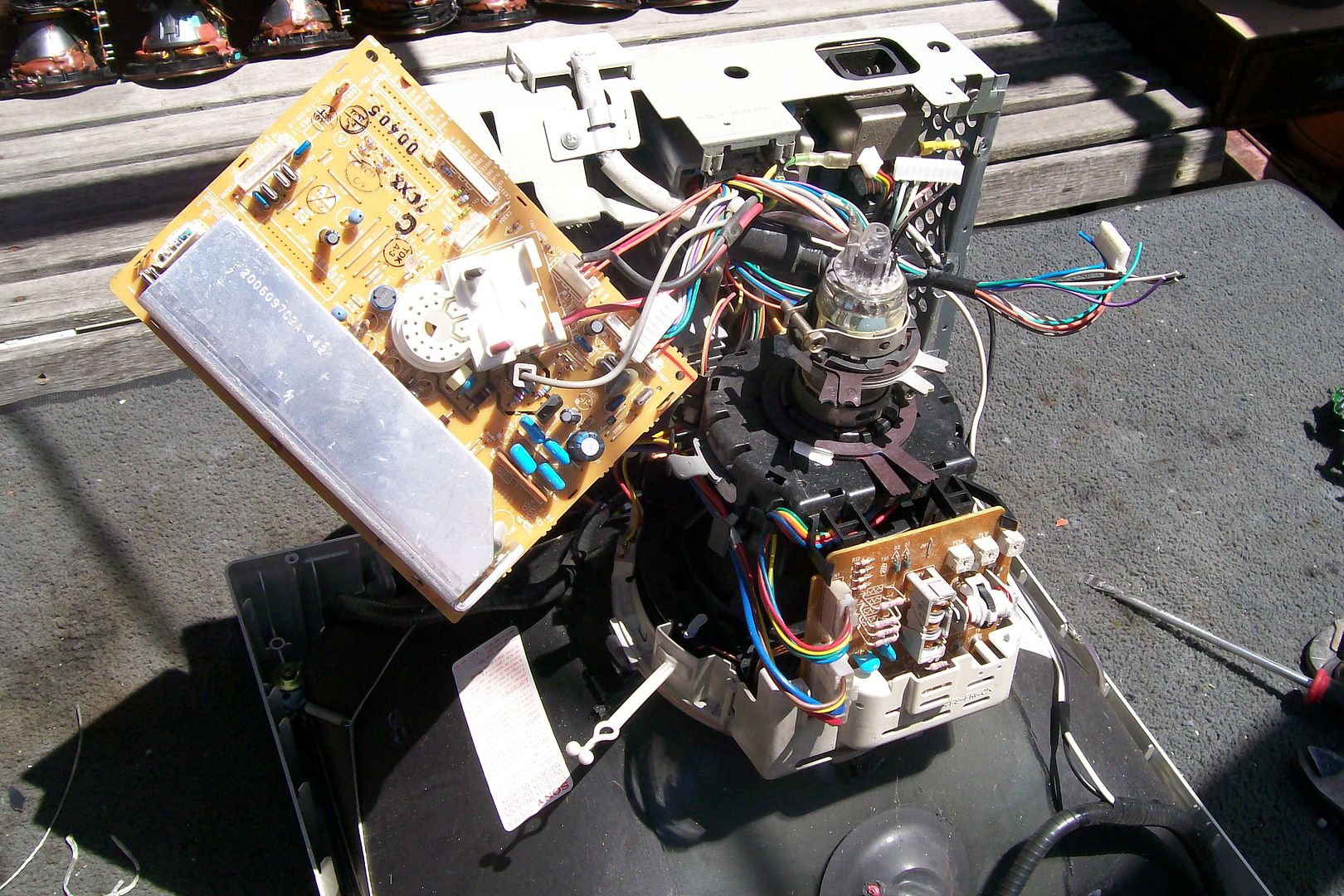 What do you guys think about instead of soldering on a connector at the very end, cutting the cable at the monitor and soldering on a female connector? I would be able to use a separate cable that way, and simply replace it if/when that one breaks. Quote:
|
|
#22
06-25-2016, 07:08 PM
|
||||
|
||||
|
Hobbyist volume soldering indoors nothing to worry about. If the flux smoke bothers you, open a window or use a fan.
Soldering a female at the monitor not a great idea, IMHO. Unless you actually install the connector into the case/chassis. Putting it on a stub of cord is harder to do mechanically, and will transfer extra load to the strain relief at the monitor housing, which can/will cause another cable failure if flexed too much. You could certainly replace the entire cable if you have an EXACT replacement scavenged from another monitor of the same type/brand. There is no "standard" as to the types/number/pinouts of the connector(s) INSIDE the monitor. Last edited by N2IXK; 06-25-2016 at 07:13 PM.
|
|
#23
06-25-2016, 08:32 PM
|
|||
|
|||
|
Excellent.
I picked up a 15-pin DSUB connector today and a connector hood. I'm all ready to go except for one thing. The hole for the cable on the hood is too small. Can I still use this hood? Where can I pick up a hood with a thicker hole?
|
|
#26
06-26-2016, 02:21 AM
|
|||
|
|||
|
Almost all of the housings I saw on Digikey look too narrow to accept this cable. The closest I could find was this.
This is the exact thickness of my cable relative to the connector (and shape of connector). 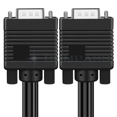 Will I be fine with the one I linked? The one from RS is too thin by far, even to dremel because the strain relief would be gone.
|
|
#27
06-26-2016, 08:47 AM
|
||||
|
||||
|
Did you check the datasheet for that connector, and compare it to your cable diameter? It says it comes with seals to fit cables from 3.5 to 7 mm.
http://www.assmann.us/specs/A-HDx15-HOOD-WP.pdf That is a waterproof industrial connector, and is EXTREME overkill for your application. It may have issues mating with a standard VGA connector on a computer (going to be physically bulky so clearance becomes an issue). And they cost $11 each! You need to MEASURE your cable diameter, and RESEARCH the various connector hoods/backshells that are available. READ datasheets, and SELECT one that will fit YOUR application. None of this is rocket science. But it takes a bit of effort to dig through datasheets and find a part that will work for you. Nobody else is going to do your research for you...
|
|
#28
08-11-2016, 10:15 AM
|
|||
|
|||
|
Thank you very much so far.
I think I've gone as far as I can without asking for help, but I don't know how to proceed. I've opened up the cable and connector and I'm ready to solder. I've found that the pinout is as follows: 1-Red-Inner Red Coaxial Wire 2-Green-Inner Green Coaxial Wire 3-Blue-Inner Blue Coaxial Wire 4-ID2-Unknown 5-Ground HSync-Outer Black Coaxial Wire 6-Red Return-Outer Red Coaxial Wire 7-Green Return-Outer Green Coaxial Wire 8-Blue Return-Outer Blue Coaxial Wire 9-Pin Missing 10-Ground Vsync-Little Black Wire 11-ID0-Unknown 12-ID1-Red Wire inside Black Coaxial Wire 13-Hsync-White Wire 14-Vsync-Brown Wire 15-ID3-Yellow Wire inside Black Coaxial Wire The connector has 13 wires, yet 14 pins. The green wire is unaccounted for. How can this be? 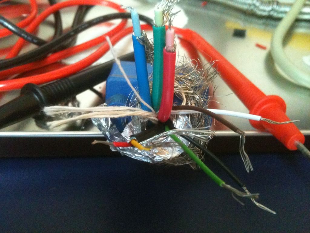 Not to mention red is apparently fine. Last edited by Outland; 08-11-2016 at 11:27 AM.
|
|
#30
08-11-2016, 12:38 PM
|
||||
|
||||
|
Check the resistance between the inner and outer conductors on each of the RGB coax cables. If the cables are good all the way into the monitor, you should read around 75 ohms on each one.
|
| Audiokarma |
 |
| Thread Tools | |
| Display Modes | |
|
|


 Linear Mode

