Videokarma.org

Go Back   Videokarma.org TV - Video - Vintage Television & Radio Forums > Vintage TV & Radio Tech Forum

Notices

We appreciate your help

in keeping this site going.
Reply
 
Thread Tools Display Modes
  #1  
Old 12-08-2016, 09:18 PM
Findm-Keepm's Avatar
Findm-Keepm Findm-Keepm is offline
Followin' the Rules...
 
Join Date: Jun 2007
Posts: 2,857
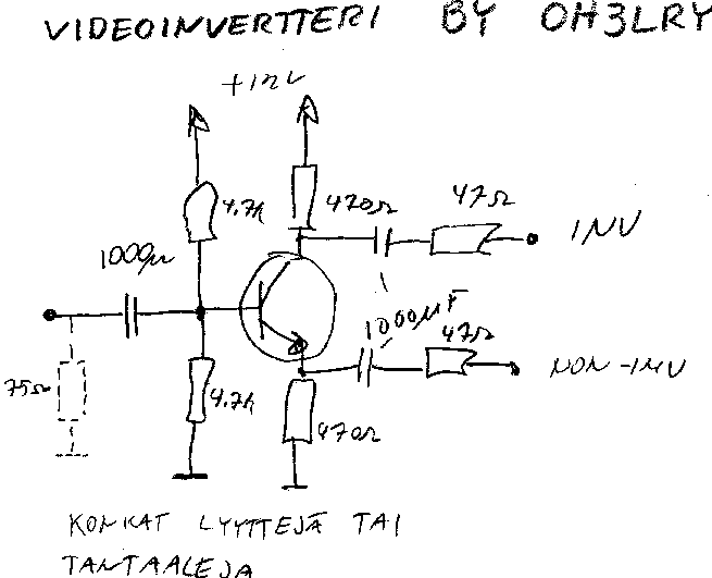
Or with a single transistor:

Video Inverter near the bottom of the list.....

http://www.hobbyprojects.com/A/video.html

I built a crosshatcht generator using an EDN magazine "Design Idea" and tried the video out with a salvaged Astec modulator - no joy, so I rigged up a 2N2222A as an inverter, and voila....


BTW, it still works, and is more stable than my RCA portable unit...
__________________
Brian
USN RET 22YRS (Avionics/Cal)
CET-Consumer Repair and Avionics ('88)
"Capacitor Cosmetologist since '79"

When fuses go to work, they quit!

Last edited by Findm-Keepm; 12-08-2016 at 09:23 PM.
Reply With Quote
  #2  
Old 12-09-2016, 07:34 AM
vts1134's Avatar
vts1134 vts1134 is offline
Looking For Time
 
Join Date: Apr 2011
Location: Pittsburgh, PA
Posts: 1,534


Would a 2N4401 work in that circuit?
__________________
John
Reply With Quote
  #3  
Old 12-09-2016, 08:03 AM
Findm-Keepm's Avatar
Findm-Keepm Findm-Keepm is offline
Followin' the Rules...
 
Join Date: Jun 2007
Posts: 2,857
Sure - any low gain (hfe<500) NPN should work. If you get any ringing, try ferrite beads on the base and collector leads.

I built my 2N2222A inverter on a double sided PCB, with the bottom as a ground plane, and "Manhattan" style construction on the top. The circuit I used was in "Circuits Cookbook" from 1967....

The whole circuit takes advantage of the common emitter configuration for inversion - and - the common collector configuration gives you the non-inverted video on the emitter. Two in one!

https://en.wikipedia.org/wiki/Common_emitter
https://en.wikipedia.org/wiki/Common_collector
__________________
Brian
USN RET 22YRS (Avionics/Cal)
CET-Consumer Repair and Avionics ('88)
"Capacitor Cosmetologist since '79"

When fuses go to work, they quit!
Reply With Quote
  #4  
Old 12-10-2016, 09:36 AM
kf4rca kf4rca is offline
VideoKarma Member
 
Join Date: Feb 2015
Location: Atlanta
Posts: 958
Probably need some gain

http://www.circuitdiagramworld.com/a...fier_4380.html
__________________
Reply With Quote
  #5  
Old 12-10-2016, 03:06 PM
vts1134's Avatar
vts1134 vts1134 is offline
Looking For Time
 
Join Date: Apr 2011
Location: Pittsburgh, PA
Posts: 1,534
Can anyone verify that the circuit I posted should work? I can't get anything out of it.
__________________
John
Reply With Quote
Audiokarma
  #6  
Old 12-10-2016, 06:50 PM
old_coot88 old_coot88 is offline
VideoKarma Member
 
Join Date: Sep 2009
Posts: 2,651
Quote:
Originally Posted by vts1134 View Post
Can anyone verify that the circuit I posted should work? I can't get anything out of it.
You mean you've built it already? If it's not working, the transistor may not be biased correctly. First measure the emitter/base voltage, which should be about 0.7 V. If the voltage is too low or missing, you need to increase value of the base-to-ground resistor.

Or, if the emitter/base voltage is too high, the transistor will overconduct and saturate. So lower the voltage by increasing value of the base-to-12V resistor.

This is all assuming the transistor is NPN silicon type and supply is +12V.

BTW, the circuit shown will deliver only half the output level that it would if the non-inverting feature (which you don't need) were eliminated. The mod would be easy to do if the output level turns out to be inadequate. Here's a neat little tutorial on transistor biasing..
http://www.electronics-tutorials.ws/...r-biasing.html

Last edited by old_coot88; 12-11-2016 at 01:07 AM. Reason: Typo
Reply With Quote
  #7  
Old 12-11-2016, 07:55 AM
vts1134's Avatar
vts1134 vts1134 is offline
Looking For Time
 
Join Date: Apr 2011
Location: Pittsburgh, PA
Posts: 1,534
Quote:
Originally Posted by old_coot88 View Post
...the circuit shown will deliver only half the output level that it would if the non-inverting feature (which you don't need) were eliminated. The mod would be easy to do if the output level turns out to be inadequate...
How would I accomplish that?
__________________
John
Reply With Quote
  #8  
Old 12-11-2016, 10:31 AM
old_tv_nut's Avatar
old_tv_nut old_tv_nut is offline
See yourself on Color TV!
 
Join Date: Jul 2004
Location: Rancho Sahuarita
Posts: 7,777
Quote:
Originally Posted by vts1134 View Post
Can anyone verify that the circuit I posted should work? I can't get anything out of it.
The problem is that the base is biased at about 1/2 of B+, which makes the emitter that (6 v) minus 0.7 volts = 5.3 v, and the collector drops to 12-5.3 = 6.7 v, so the transistor is almost saturated at one end of the circuit's output range. You need to reduce the lower base resistor or increase the top one to get about 3.7 volts at the base. Then the emitter will be at 3 volts and be able to swing almost from ground to 6 volts, while the collector will be at 9 volts and be able to swing almost from 6 to 12 volts.

You could try leaving the lower base resistor as 4.7k and increasing the upper one to 15k or 18k.
__________________
www.bretl.com
Old TV literature, New York World's Fair, and other miscellany
Reply With Quote
  #9  
Old 12-11-2016, 11:21 AM
kf4rca kf4rca is offline
VideoKarma Member
 
Join Date: Feb 2015
Location: Atlanta
Posts: 958
I always use a pot...

say 100K or so and adjust it till I get what I want with a scope on the output. Then measure the pot and substitute fixed resistors.
__________________
Reply With Quote
Reply


Thread Tools
Display Modes

Posting Rules
You may not post new threads
You may not post replies
You may not post attachments
You may not edit your posts

BB code is On
Smilies are On
[IMG] code is On
HTML code is Off

Forum Jump


All times are GMT -5. The time now is 08:12 AM.


Powered by vBulletin® Version 3.8.4
Copyright ©2000 - 2026, Jelsoft Enterprises Ltd.
©Copyright 2012 VideoKarma.org, All rights reserved.