
|
|
|
|
|
#1
 03-11-2017, 08:08 PM
|
||||
|
||||
|
You could probably apply 6.3V heater current to a voltage doubler, then apply the ~12VDC form the doubler to a simple LM317 based regulator circuit to drop it to 9V and eliminate ripple (with suitable caps in the input and output of the reg)... Just watch for DC potentials on the heater line from preexisting circuits, and Heater cathode breakdown voltages.
[EDIT] Seems others beat me to my first point...I still recommend having that active regulator there to reduce hum.
__________________
Tom C. Zenith: The quality stays in EVEN after the name falls off! What I want. --> http://www.videokarma.org/showpost.p...62&postcount=4 
|
|
#2
03-12-2017, 02:20 PM
|
||||
|
||||
|
Phil; I've gone back and read through this conversation and I thought I would add some things. Before you go too far with this it would be a good idea to measure the DC voltages on the transistor. My back of a envelope calculations indicates the collector might be sitting at more than 8 V if the supply is 9 V, which would leave little "head room". My calculations predict a current draw for this circuit is about 3 ma. Also you can't expect very good high frequency performance with the long wires in your test setup.
|
|
#3
03-12-2017, 07:01 PM
|
||||
|
||||
|
Thanks, I measured those DC voltages and got 4.9V at the collector, 2.8V at the base, and 2.0V at the emitter.
If I decide to install this gizmo, I'll certainly use much shorter leads. Regarding a voltage regulator for a 9V p-s, are we talking about something like the following? 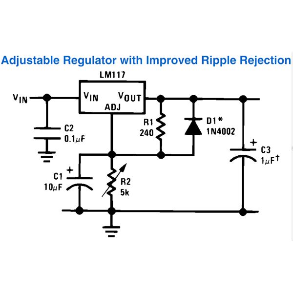 Regards, Phil Nelson
|
|
#4
03-12-2017, 08:03 PM
|
|||
|
|||
|
Considering the low current draw of that one transistor, all you need is a simple half wave supply using a diode and filter cap. A fancy active regulator is good when you're dealing with high current draw.
Others' opinions may vary. 
|
|
#5
03-12-2017, 08:47 PM
|
||||
|
||||
|
Here is a link to a three pin fixed 9 V regulator. You only need to add two capacitors to it. Part of the 78L series. The TO-92 package (transistor size) can provide 100 ma.
http://www.digikey.com/product-detai...1-1-ND/5253742 Phil, thanks for the voltage readings. Its good documentation for the future. However I'm not sure everything adds up. You are using 10K, 4.7K, 820 and 3.3K resistors and a 9 V supply?
|
| Audiokarma |
|
#6
03-13-2017, 11:04 AM
|
||||
|
||||
|
I think I know why your voltage readings didn't make sense to me. First I made a math mistake, but also I thought you built old_coot88's version and I guess you built vts1134's. In that version the collector voltage varies as you adjust the pot to change the AC gain. I think if you check, the pot was adjusted to about 1.6K. That would mean the AC gain is about 2 instead of about 4 with the pot at 3.3K. Anyway you can't argue with success!
 More on that regulator; you can see the relevant data by clicking on the link on that page. The pages for the 9V version is on pages 4 and 9. You need at least a 0.33 uf on the input and at least 0.1 uf on the output. The regulator should be fed by at least 12 V.
|
|
#7
03-14-2017, 06:57 PM
|
||||
|
||||
|
Quote:
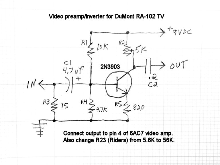 The preamp/inverter seems to work well using either a 9V or 12V battery. As for powering it from the TV chassis rather than a battery, old_coot88 suggested: Quote:
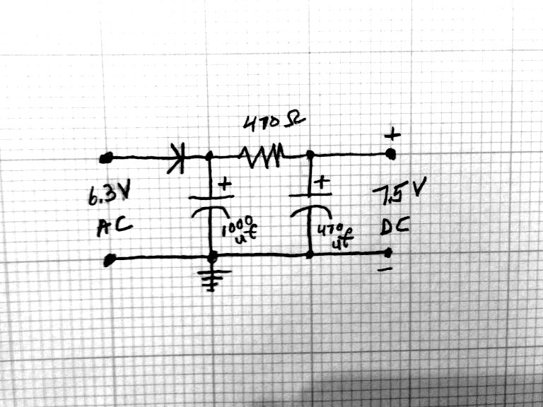 Using only one filter cap produced a faint moving hum bar, so I added a second. The preamp/inverter seems to work at this lower supply voltage (around 7.5V DC), although so far I haven't looked at anything except test patterns. This is an interesting experiment, but I don't know whether I'll install this preamp/inverter. Yes, injecting the video produces a somewhat better picture, but the improvement is incremental, not night-and-day. In its current condition, the TV makes a watchable (although not perfect) picture without injection, as seen in this photo and video clip that I took a while back. 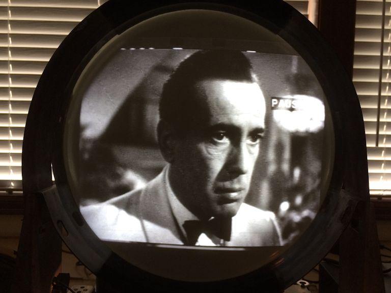 http://antiqueradio.org/art/DuMontRA...inaryInput.mp4 (The horizontal bands in the video are camera artifacts.) I've been slogging along with this project for a VERY long time. It would be nice to get this whale off my workbench and putter with something else for a change. Maybe I'll put the TV in its cabinet and try watching for a while. If I can't live with it, I can always install the A/V patch later. Thanks, Phil Nelson Phil's Old Radios http://antiqueradio.org/index.html
|
|
#8
03-14-2017, 07:21 PM
|
||||
|
||||
|
|
|
#9
03-14-2017, 08:42 PM
|
||||
|
||||
|
Quote:
|
|
#11
04-02-2017, 06:13 PM
|
||||
|
||||
|
After a few more tweaks, I declared victory on the electronic front and put the RA-102 into its cabinet. I posted an article about the restoration here:
http://antiqueradio.org/DuMontRA-102...Television.htm I'll refinish the cabinet when the weather improves. Thanks to everyone for the generous advice, in this thread and others. Now I can launch the next project -- an Emerson 609 projection TV! Regards, Phil Nelson Phil's Old Radios http://antiqueradio.org/index.html 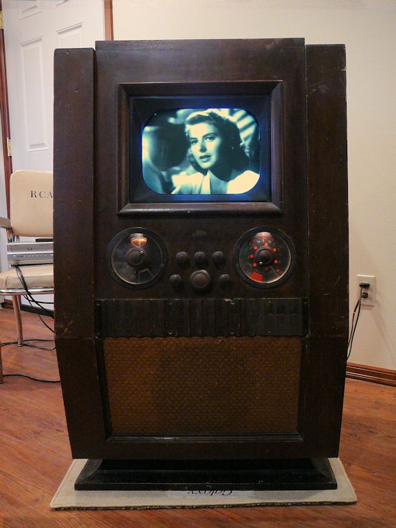 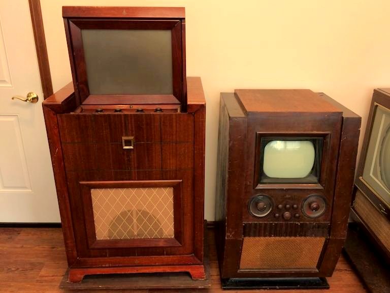
|
 |
| Thread Tools | |
| Display Modes | |
|
|








 Hybrid Mode
