
|
|
|
|
|
#1
 03-12-2017, 07:01 PM
|
||||
|
||||
|
Thanks, I measured those DC voltages and got 4.9V at the collector, 2.8V at the base, and 2.0V at the emitter.
If I decide to install this gizmo, I'll certainly use much shorter leads. Regarding a voltage regulator for a 9V p-s, are we talking about something like the following? 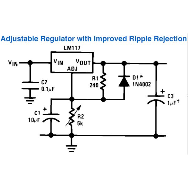 Regards, Phil Nelson 
|
|
#2
03-12-2017, 08:03 PM
|
|||
|
|||
|
Considering the low current draw of that one transistor, all you need is a simple half wave supply using a diode and filter cap. A fancy active regulator is good when you're dealing with high current draw.
Others' opinions may vary. 
|
|
#3
03-12-2017, 08:47 PM
|
||||
|
||||
|
Here is a link to a three pin fixed 9 V regulator. You only need to add two capacitors to it. Part of the 78L series. The TO-92 package (transistor size) can provide 100 ma.
http://www.digikey.com/product-detai...1-1-ND/5253742 Phil, thanks for the voltage readings. Its good documentation for the future. However I'm not sure everything adds up. You are using 10K, 4.7K, 820 and 3.3K resistors and a 9 V supply?
|
|
#4
03-13-2017, 11:04 AM
|
||||
|
||||
|
I think I know why your voltage readings didn't make sense to me. First I made a math mistake, but also I thought you built old_coot88's version and I guess you built vts1134's. In that version the collector voltage varies as you adjust the pot to change the AC gain. I think if you check, the pot was adjusted to about 1.6K. That would mean the AC gain is about 2 instead of about 4 with the pot at 3.3K. Anyway you can't argue with success!
 More on that regulator; you can see the relevant data by clicking on the link on that page. The pages for the 9V version is on pages 4 and 9. You need at least a 0.33 uf on the input and at least 0.1 uf on the output. The regulator should be fed by at least 12 V.
|
|
#5
03-14-2017, 06:57 PM
|
||||
|
||||
|
Quote:
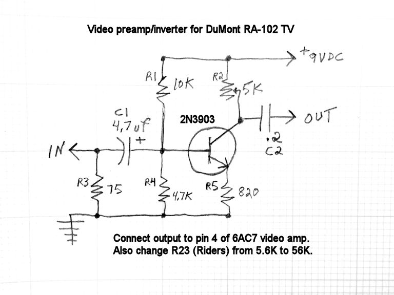 The preamp/inverter seems to work well using either a 9V or 12V battery. As for powering it from the TV chassis rather than a battery, old_coot88 suggested: Quote:
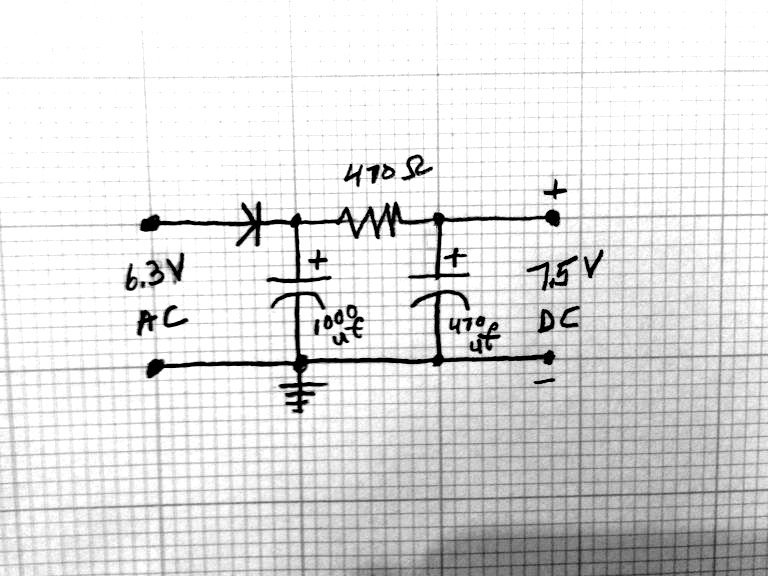 Using only one filter cap produced a faint moving hum bar, so I added a second. The preamp/inverter seems to work at this lower supply voltage (around 7.5V DC), although so far I haven't looked at anything except test patterns. This is an interesting experiment, but I don't know whether I'll install this preamp/inverter. Yes, injecting the video produces a somewhat better picture, but the improvement is incremental, not night-and-day. In its current condition, the TV makes a watchable (although not perfect) picture without injection, as seen in this photo and video clip that I took a while back. 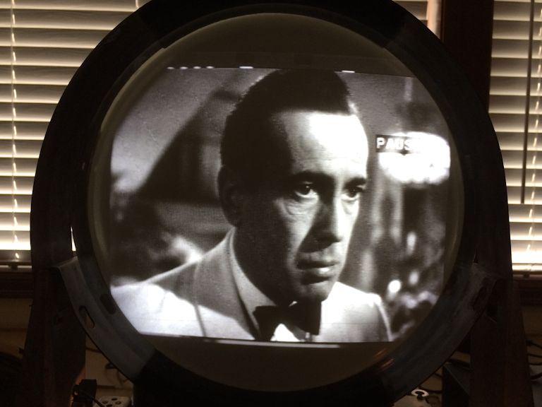 http://antiqueradio.org/art/DuMontRA...inaryInput.mp4 (The horizontal bands in the video are camera artifacts.) I've been slogging along with this project for a VERY long time. It would be nice to get this whale off my workbench and putter with something else for a change. Maybe I'll put the TV in its cabinet and try watching for a while. If I can't live with it, I can always install the A/V patch later. Thanks, Phil Nelson Phil's Old Radios http://antiqueradio.org/index.html
|
| Audiokarma |
 |
| Thread Tools | |
| Display Modes | |
|
|





 Hybrid Mode
