
|
|
|
|
|
#2
 05-09-2017, 07:24 PM
|
||||
|
||||
|
After replacing the factory-installed electrolytic and paper caps on my Emerson 609, I'm looking at this big .25-mfd paper cap, evidently added by some sloppy repairman:
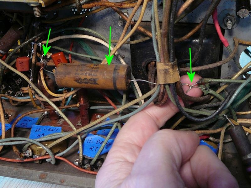 The cap isn't shown in either Riders or Sams. It's hard to trace things in this messy chassis full of long, wandering leads. But as near as I can make out, the guy wired this new cap in parallel with the Horizontal Size adjuster coil (L-8 in Riders): 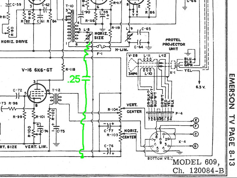 Any ideas as to why someone would add this? Tacking stuff onto a width coil suggests an attempt to get more (or less?) width, at first glance . . . . I normally remove mods and restore things to match the schematic, especially messy work like this, on the theory that the repairman was attempting a quick fix for some symptom that will be cured by the time I'm done recapping, etc. But if someone thinks this is a great improvement, I suppose I could try a new .25 cap there. You can read the full schematic here: http://antiqueradio.org/art/Emerson6...maticSmall.jpg Regards, Phil Nelson Phil's Old Radios http://antiqueradio.org/index.html 
|
|
#4
05-10-2017, 05:02 PM
|
||||
|
||||
|
OK, that rogue cap is gone.
In preparation for powering up, I checked out the five-element ballast (Emerson # 397023). Most of the elements test bad. There's a lot of corrosion where the elements join the pin leads. Even if I could coax it back into life, this doesn't seem like a good bet for long-term reliability: 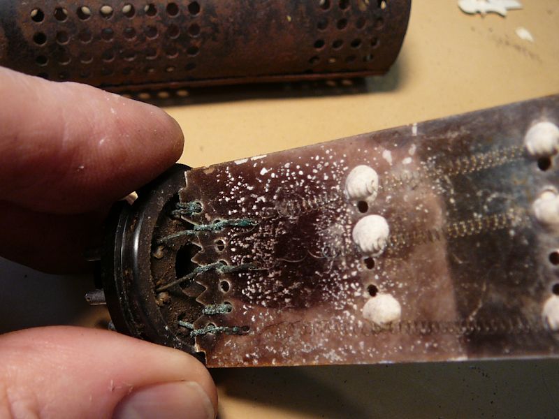 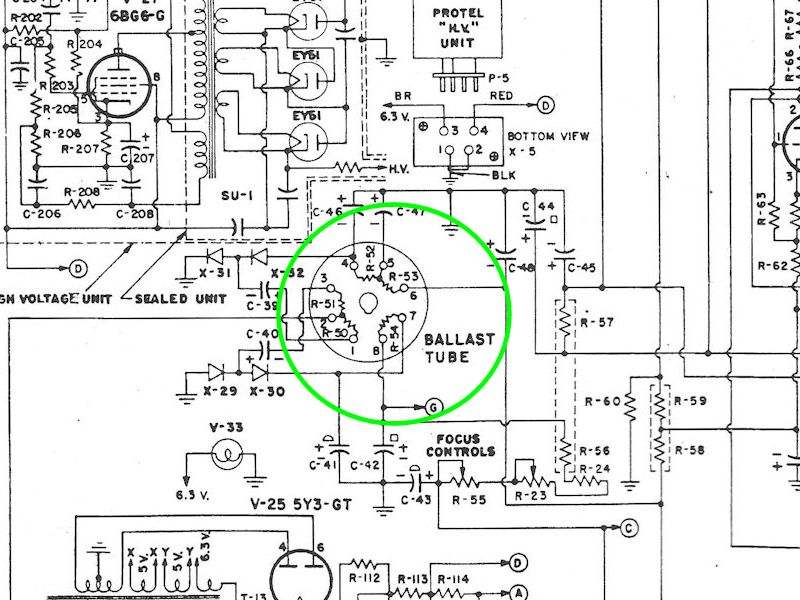 I found an eBay supplier with a Clarostat ballast, so let's hope that one works. Can't wait! Phil Nelson Phil's Old Radios http://antiqueradio.org/index.html Last edited by Phil Nelson; 05-19-2017 at 01:25 AM.
|
|
#5
05-20-2017, 01:05 AM
|
||||
|
||||
|
It's alive!
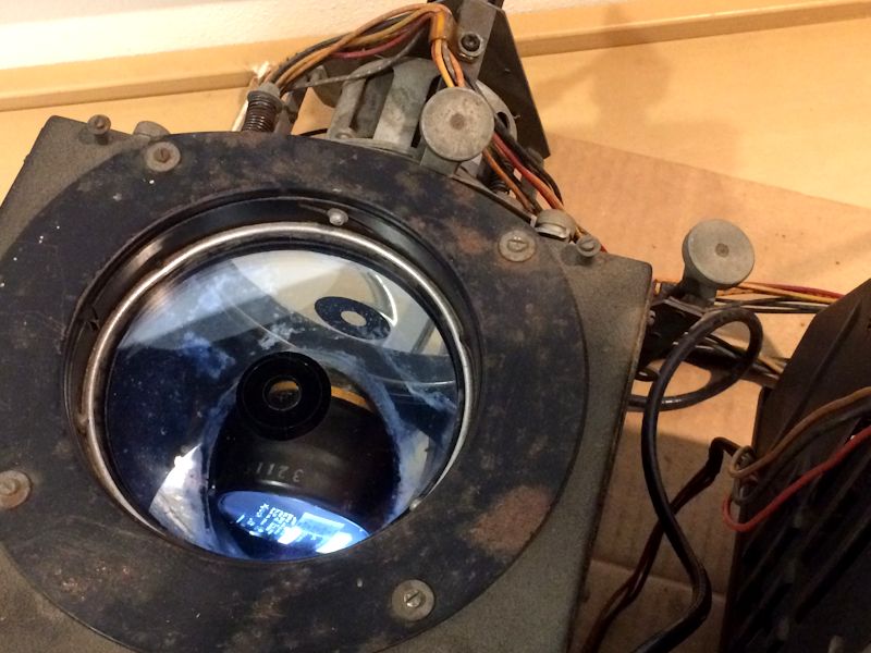 OK, that looks underwhelming, but it's exciting to me. After replacing the ballast and doing, well, a bunch of other stuff, tonight I saw the first coherent image on the Emerson's little 3NP4 CRT. (That's the Xfinity cable TV guide screen, in case you're wondering). With the chassis spread all over the workbench, there's nothing to project on (the ceiling's much too far away to focus). So peering slantwise down into the Protelgram optic box is the only way to see what's happening. This set had more problems than I had noticed at first, including an under-chassis meltdown that burned everything around the sockets of the vertical and 1st video IF tubes. But now, the vertical & horizontal are stable, brightness & contrast work as advertised, and the audio is excellent. There's more checking and tweaking to do, but it's always fun to see the first signs of life. Phil Nelson Phil's Old Radios http://antiqueradio.org/index.html Last edited by Phil Nelson; 05-20-2017 at 01:21 AM.
|
| Audiokarma |
|
#7
06-02-2017, 06:53 PM
|
||||
|
||||
|
After recapping & whatnot, the electronics are working pretty well on my Emerson 609. The optical (Norelco Protelgram) portion . . . not so wonderful.
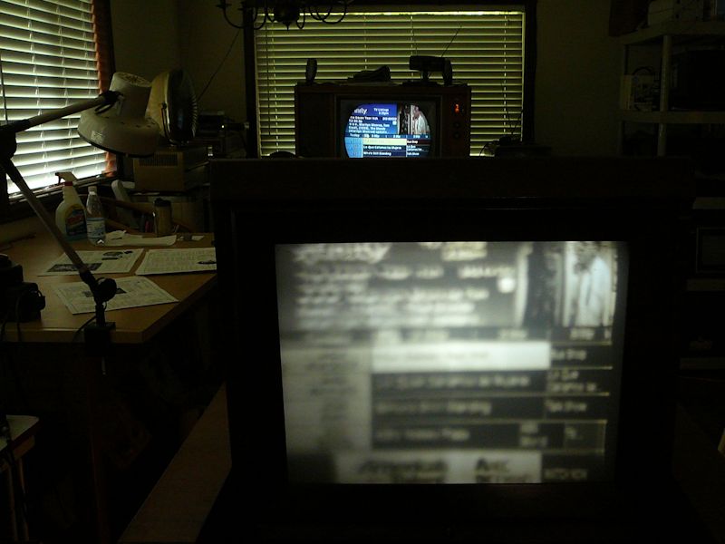 Apart from issues like bad horizontal linearity, which is only an adjustment, the image is not only dim, but unable to focus despite fiddling with the electronic and mechanical focus adjusters. The 45-degree mirror in the optics box appears to be in bad shape: 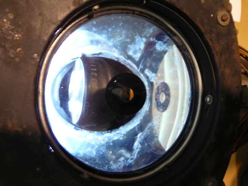 Is this the mirror that people send out to be resilvered? If so, where? I haven't made any attempt to clean it, having read horror stories in the past about people who destroyed projection TV components by inappropriate cleaning. Phil Nelson Phil's Old Radios http://antiqueradio.org/index.html
|
 |
| Thread Tools | |
| Display Modes | |
|
|




 Hybrid Mode
