
|
|
|
|
|
#1
 07-12-2017, 05:02 PM
|
|||
|
|||
|
The yoke cover is in sad shape. The back face is completely crumbled. The centering ring and holder is separated.
  My buddy thinks he might have a good one for me but it won't be till the weekend for him to see. So I decided to make one. I was going to use the plastic approach like Bob Andersen did but couldn't find the right plastic. So I made one with the materials I had at hand. I had some 1/16 thick phenolic, some 1/64 plywood, some 1/32 plywood, and some PVC sprinkler pipe that I use when re-stuffing E-caps. I first drew it out using my CAD program. Then printed out the parts and tacked them onto the phenolic. I cut them out and filed and sanded them to shape. Once the rings were made I decided that 2 layers of 1/64 plywood would work as the "rims" with the butt joints 180 degrees apart. For the "clamping" part I used some PVC sprinkler pipe but the O.D. was just a little too big and it has a wall thickness of 1/16 inch. I thought that that might be too thick and it needed to be 1/32 wall thickness. I rotated a 1 inch long piece up against my disc sander and sanded down the pipe to 1/32 wall. It is easier than you think. Just have to keep checking your progress. I then used some super glue to glue on the large rim, then the other rim on top of the first. I soaked the super glue down the joint between the two pieces. I then sanded it down to the correct height and drew a 1/8 line along the edge for the tabs. The tabs are 3/8 wide 90 degrees apart. I used my Dremel with a 1/2 sanding drum to sand away that 1/8 inch between the tabs. A small hand file was used to get the corners of the tabs. I then used some 15 minute epoxy to form a fillet along the inside edge for strength. I did the same for the centering ring holder portion. I drilled 1/8 holes in the sprinkler pipe every 3/8 inch to from the fingers. I then used a #11 blade in my hobby knife to cut the slots. This was then epoxied in place. The wooden parts were given a soaking of super glue to seal them, a light sanding and then some primer. Again some light sanding and some gloss black will complete the assembly. The black is drying as I type.        
Last edited by Crist Rigott; 07-12-2017 at 05:07 PM. 
|
|
#2
07-12-2017, 07:33 PM
|
||||
|
||||
|
Impressive work, Crist!
|
|
#3
07-12-2017, 08:22 PM
|
|||
|
|||
|
Quote:
|
|
#4
07-12-2017, 08:24 PM
|
||||
|
||||
|
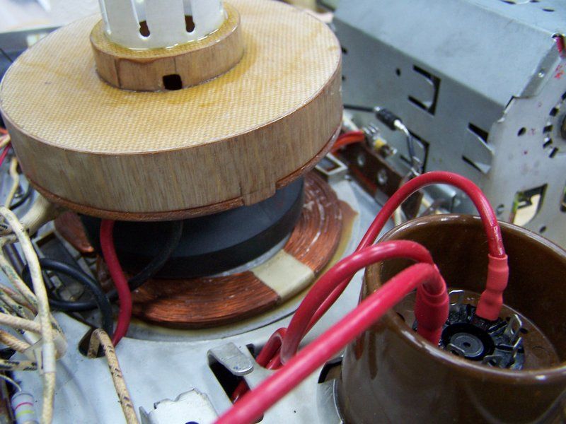
Very nice work. I'm just worried about that flyback. What are the three wires going to the second anode?
__________________
"Tubes are those little glass things that light up orange unless there is a short.. Then they light up all pretty colors..." Please join my forum. http://www.tuberadioforum.com/
|
|
#5
07-12-2017, 08:29 PM
|
|||
|
|||
|
Quote:
I'm not sure what 3 wires you are talking about. There's a red one, and black one which goes to the yoke, and I think there's a white one and I'm not sure where it goes. I have the cover on the HV cage.
|
| Audiokarma |
|
#6
07-12-2017, 08:33 PM
|
||||
|
||||
|
Where does the black wire come from? If it's the yoke, very likely it goes to one of the taps on the flyback.
__________________
"Tubes are those little glass things that light up orange unless there is a short.. Then they light up all pretty colors..." Please join my forum. http://www.tuberadioforum.com/
|
|
#7
07-12-2017, 09:28 PM
|
|||
|
|||
|
Quote:
|
|
#8
07-13-2017, 10:21 PM
|
||||
|
||||
|
Quote:
__________________

|
|
#9
07-13-2017, 10:55 PM
|
|||
|
|||
|
Quote:
|
 |
| Thread Tools | |
| Display Modes | |
|
|


 Hybrid Mode
