Videokarma.org

Go Back   Videokarma.org TV - Video - Vintage Television & Radio Forums > Early B&W and Projection TV

Notices

We appreciate your help

in keeping this site going.
Reply
 
Thread Tools Display Modes
  #1  
Old 01-08-2018, 07:05 PM
robert1's Avatar
robert1 robert1 is offline
VideoKarma Member
 
Join Date: Jan 2005
Location: Wild Wonderful West Virginia
Posts: 134
Quote:
Originally Posted by bandersen View Post
However, I did notice a strange issue. As I decreased the brightness, it dimmed more on the sides than the center.

You can get it down to where there is just a think strip visible in the middle.

I'm thinking the HV doorknob cap way be bad or there is some ripple in the power supply. There are still a few old electrolytics left. I'l tr replacing them first.
I believe that there is a bad electrolytic capacitor for the video output cathode bias that is bad. i've seen this before. if the doorknob capacitor is failing, there would be HV issues, but from what i see of the pics, this is more like a problem with the video output stages. i would venture to say that a total recap of the set will fix the problem.
Reply With Quote
  #2  
Old 01-09-2018, 12:22 PM
bandersen's Avatar
bandersen bandersen is offline
RCA 741PCS
 
Join Date: Mar 2009
Location: Chicago, IL
Posts: 8,808
Quote:
Originally Posted by robert1 View Post
I believe that there is a bad electrolytic capacitor for the video output cathode bias that is bad. i've seen this before. if the doorknob capacitor is failing, there would be HV issues, but from what i see of the pics, this is more like a problem with the video output stages. i would venture to say that a total recap of the set will fix the problem.
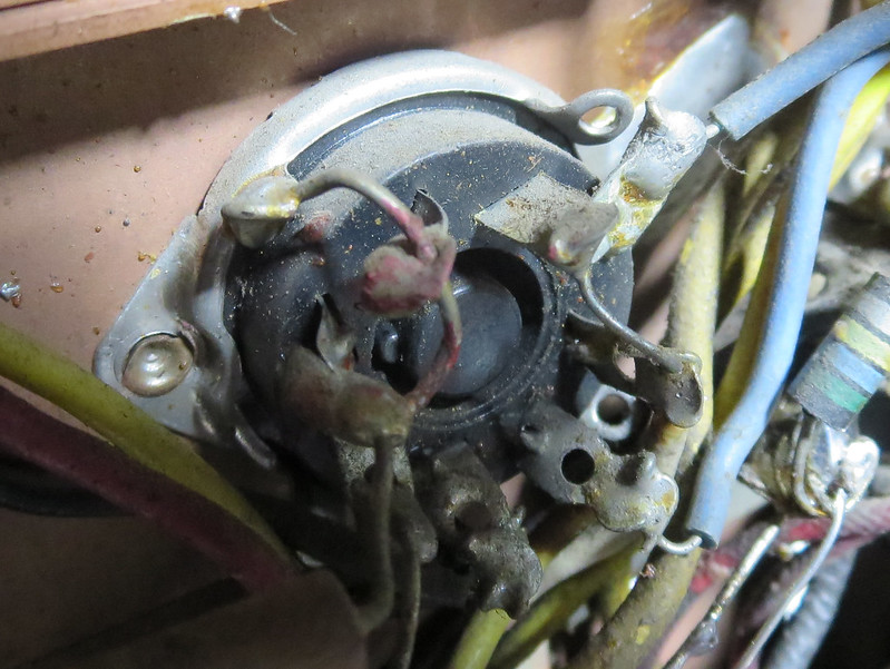
You were close. There is no cathode bias cap on the 6AC7 video output tube, but the problem was a filter cap. While investigating, I was surprised to see that the filament ground wire on pin 2 wasn't soldered. It also appears to have Glyptal (red insulating varnish) paint on it Weird. It must be making good enough contact because the tube is warm. I cleaned off the gunk and soldered it securely.


I then went hunting with a scope and found a huge 200V triangle waveform at around 15.75 kH on the B+ boost rail. The old 20uF cap still wired in must be dead. I temporarily tacked in a new 22uF and viola - problem solved.


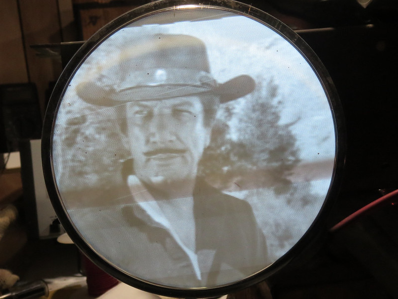
I have a few more old caps to replace then I'll check the alignment before installing a new 16GP4.

Normally, I would do a shotgun recap but I find it can be fun and instructive to do it in stages too.

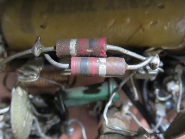
One other thing I've noticed in this and other 1950 era TVs is a weird assortment of resistors. Also some in series or parallel to get the needed value.

They must have really been hurting for 1K resistors. A bunch are actually 1.2K and here are two 2K in parallel. They even used a dogbone.


I thought this was a ceramic cap at first, but no, it's a 2.2 M resistor.


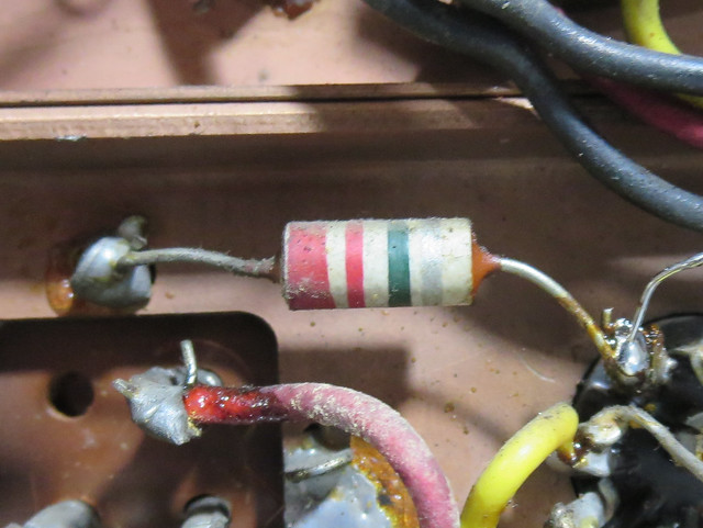
I figure the big demand for consumer electronics and the Korean war was causing shortages.
__________________
Here are my Vintage Radio & TV YouTube Channel and Photo Gallery

Last edited by bandersen; 01-09-2018 at 03:23 PM.
Reply With Quote
Reply


Thread Tools
Display Modes

Posting Rules
You may not post new threads
You may not post replies
You may not post attachments
You may not edit your posts

BB code is On
Smilies are On
[IMG] code is On
HTML code is Off

Forum Jump


All times are GMT -5. The time now is 11:23 AM.


Powered by vBulletin® Version 3.8.4
Copyright ©2000 - 2026, Jelsoft Enterprises Ltd.
©Copyright 2012 VideoKarma.org, All rights reserved.