
|
|
|
|
|
#1
 05-19-2020, 06:50 PM
|
||||
|
||||
|
If I am remembering inductors correct, a resistance at or right next to 0 is fine.
I'd be verifying that it's not the transformer at fault as you know the wrong voltage is comping out of it, but you didn't say what was going in. I believe the tap numbering is listed in the service manual. Also verify your entire bank of fuses are good with a continuity check. Sometimes when I get weird voltages on a feed circuit it's a cartridge fuse that's gone bad. 
|
|
#2
05-20-2020, 01:17 PM
|
||||
|
||||
|
Quote:
I have not checked all fuses on every board, but only the one fuse on the ACRY board. Continuity on that fuse checks OK. I attached an image. The posts in the red square are where I tested and showed 47VAC rather than the 120VAC as stated. That CN550 connection is where the transformer attaches. Last edited by cornponious; 05-20-2020 at 01:24 PM.
|
|
#3
05-20-2020, 01:32 PM
|
||||
|
||||
|
Quote:
And here is the inductor in question. I can't even find any information online for how to determine the inductance of this coil, regarding the specific text on the side. Nothing I have found seems to match the type of text on the inductor. And there are no other markings anywhere on this inductor. It's very confusing to me.
|
|
#4
05-20-2020, 06:48 PM
|
||||
|
||||
|
I mean, if the inductor was shorted between windings you'd know of it pretty quickly as that's high current 120v.
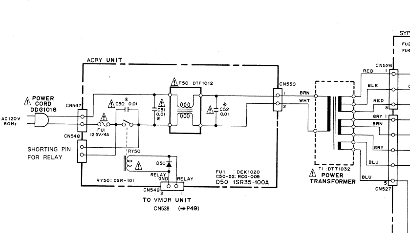 I am assuming you have the relay bypass jumper installed when testing? Otherwise your circuit breaks at the relay.
|
|
#5
05-22-2020, 01:28 PM
|
||||
|
||||
|
Quote:
You shouldn't assume. I'm just a step or two above novice. :-P No, I am not shorting the pins. So, I should do this when the board is not installed in the unit and I'm testing? Should I short it when the board is plugged in to the wall? It's just something I'm not familiar with and I apologize for coming across so ignorant. If I'm wrong here, would you mind explaining to me the process of using this shorting pin, and when I would use it? Also, where did you get that diagram? I did not see that in the service manual. I guess I could have missed it though. Also also, thank you for taking time to converse with me about this. I'm just excited about owning this, and really want to get it working. I'll short those pins and then report back what I find.
__________________
I have a stupid motovlog. It's really stupid. Please subscribe (if you want). I'm begging. The MotoDork Last edited by cornponious; 05-22-2020 at 01:33 PM.
|
| Audiokarma |
|
#6
05-22-2020, 08:39 PM
|
||||
|
||||
|
Not a problem. Any pool of knowledge is better than seemingly yelling into the void.
 The diagram is near the back of the service manual mixed in with the PCB layouts. The jumper bypasses the need for the CO-V300 or similar to be attached. It delivers the voltage which closes the relay and allows the autochanger to power on. Without the controller attached or powered on the relay can't close so the jumper just bypasses the relay entirely.
|
|
#7
05-23-2020, 12:33 PM
|
||||
|
||||
|
Quote:
Do i need to have that jumper on to make this thing work since I don't have the commander? Am I this much of a dumbass?
__________________
I have a stupid motovlog. It's really stupid. Please subscribe (if you want). I'm begging. The MotoDork
|
|
#8
05-23-2020, 01:12 PM
|
||||
|
||||
|
Yes, the commander is required both to turn the LC-V300 on AND to command it to operate, otherwise it has no way on its own to be manually operated as a standalone device.
This is why I had to cave in and ship a commander from the opposite corner of the pacific. One thing I found out is that unless you are doing nothing but karaoke the commander is not really all that useful otherwise as it's programmed to handle LaserKaraoke discs and lacks most of the standard commands you expect from a laserdisc player, like pause and frame select. The service manual however states this is not something hard-coded to the autochanger. Pioneer also had a service tool that let someone completely substitute the commander in a technical service perspective and it includes all the standard laserdisc commands. I have never seen the tool and don't know what its part number was but presumably if you crack its secrets suddenly you can make the LC-V300 be a 72 disc laserdisc player and the possibilities stem from there. Mind you, a serial interface may also already exist as well since the LC-V300 was also available in an industrial package. The closest thing I can find is the Pioneer LC-V330 which on the outside is visually identical to the V300 aside from the laserkaraoke badging and front window removed, there are conflicting reports on how many discs it can hold and while I DO have the MS-DOS software that lets you control one over a serial port (you can find it here), that I can tell it uses a different commander interface with the more standard 15 pin connector instead of the 25 pin port the V300 uses. There's still a lot of presumably Pioneer documented but not available online mysteries. Edited: Pioneer lists that the service manual for the LC-V330 does exist but is not available for download - http://parts.pioneerelectronics.com/...uctNum=ARP1666 Last edited by MIPS; 05-23-2020 at 01:30 PM.
|
 |
| Thread Tools | |
| Display Modes | |
|
|


 Hybrid Mode
