Videokarma.org

Go Back   Videokarma.org TV - Video - Vintage Television & Radio Forums > Solid State CRT Televisions

Notices

We appreciate your help

in keeping this site going.
Reply
 
Thread Tools Display Modes
  #1  
Old 08-13-2026, 05:05 PM
pac.attack76's Avatar
pac.attack76 pac.attack76 is offline
Stuck in the past
 
Join Date: Mar 2013
Location: Michigan
Posts: 1,311
Quote:
Originally Posted by vol.2 View Post
In that case, I would remove the control from the circuit and test it for continuity with a DMM.

If you can rule out that the control as a problem, then you can focus on other things.

Assuming the control is okay, then my next step would be to check from the chroma signal out of the demodulation area. I personally wouldn't attempt it without a schematic though

There are other guys on this forum who might be able to point you at some part to check after that or not, but it's going to get increasingly more complex as you rule out low hanging fruit like a bad control
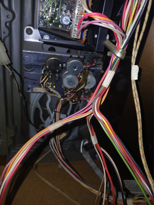
You mean that top left looking from the back? Also looks like its had a history with color problems. Some changed the board out and left the old one inside...


__________________
Genesis does what Nintendon't
Reply With Quote
  #2  
Old 08-13-2026, 07:32 PM
vol.2's Avatar
vol.2 vol.2 is offline
VideoKarma Member
 
Join Date: Feb 2023
Posts: 427
Quote:
Originally Posted by pac.attack76 View Post
You mean that top left looking from the back? Also looks like its had a history with color problems. Some changed the board out and left the old one inside...
Yes. You can probably get a decent idea of how it's working by measuring it without taking it out first.

Take you multimeter and measure across the whole pot to see what the resistance is, and then measure between the wiper and either side. find a way to clip the meter leads onto the terminals of the pot and turn the pot from side to side while looking at the meter. You should see the resistance change smoothly from one end of the pot to the other.

Based on what you have already said though, I would expect it to be completely shorted, or completely open if there's a problem with it at all.

If you can confirm that's it's behaving like a normal pot, then you can pretty much assume it's not broken and move on.

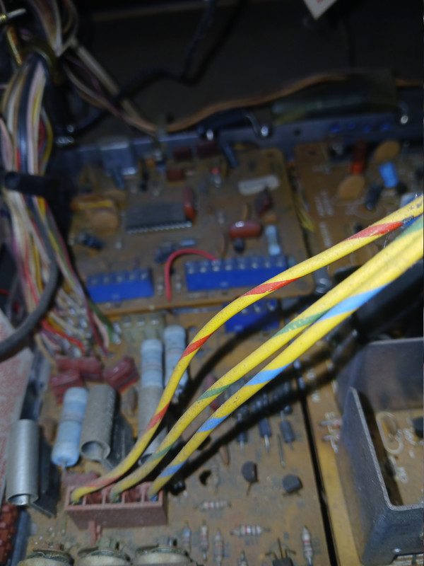
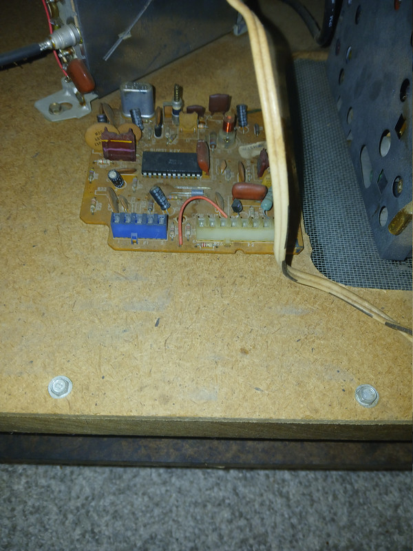
Looking at those other pictures, it seems like those old boards might need all the connectors cleaned really well, and the solder joints reflowed on anything that looks bad or is a physical connector.

Solder joints tend to fail on parts that are either heavy or take abuse, like connectors that get done and undone, and big heavy parts like the flyback or transformer, or big power resistors. You also want to check things that get hot, especially if they have been darkened or burned.

A lot of these kinds of issues will come down to basic stuff like that. Anything more advanced is probably going to require schematics.
Reply With Quote
  #3  
Old 08-15-2026, 09:00 AM
pac.attack76's Avatar
pac.attack76 pac.attack76 is offline
Stuck in the past
 
Join Date: Mar 2013
Location: Michigan
Posts: 1,311
Quote:
Originally Posted by vol.2 View Post
Yes. You can probably get a decent idea of how it's working by measuring it without taking it out first.

Take you multimeter and measure across the whole pot to see what the resistance is, and then measure between the wiper and either side. find a way to clip the meter leads onto the terminals of the pot and turn the pot from side to side while looking at the meter. You should see the resistance change smoothly from one end of the pot to the other.

Based on what you have already said though, I would expect it to be completely shorted, or completely open if there's a problem with it at all.

If you can confirm that's it's behaving like a normal pot, then you can pretty much assume it's not broken and move on.

Looking at those other pictures, it seems like those old boards might need all the connectors cleaned really well, and the solder joints reflowed on anything that looks bad or is a physical connector.

Solder joints tend to fail on parts that are either heavy or take abuse, like connectors that get done and undone, and big heavy parts like the flyback or transformer, or big power resistors. You also want to check things that get hot, especially if they have been darkened or burned.

A lot of these kinds of issues will come down to basic stuff like that. Anything more advanced is probably going to require schematics.
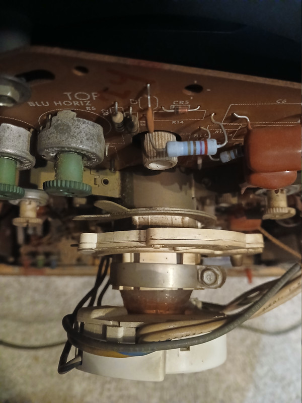
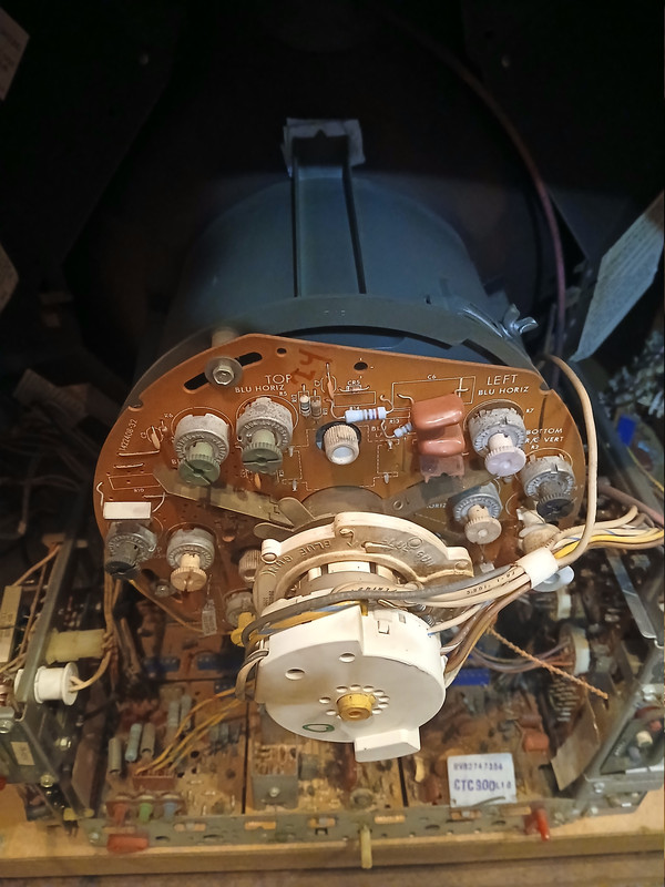
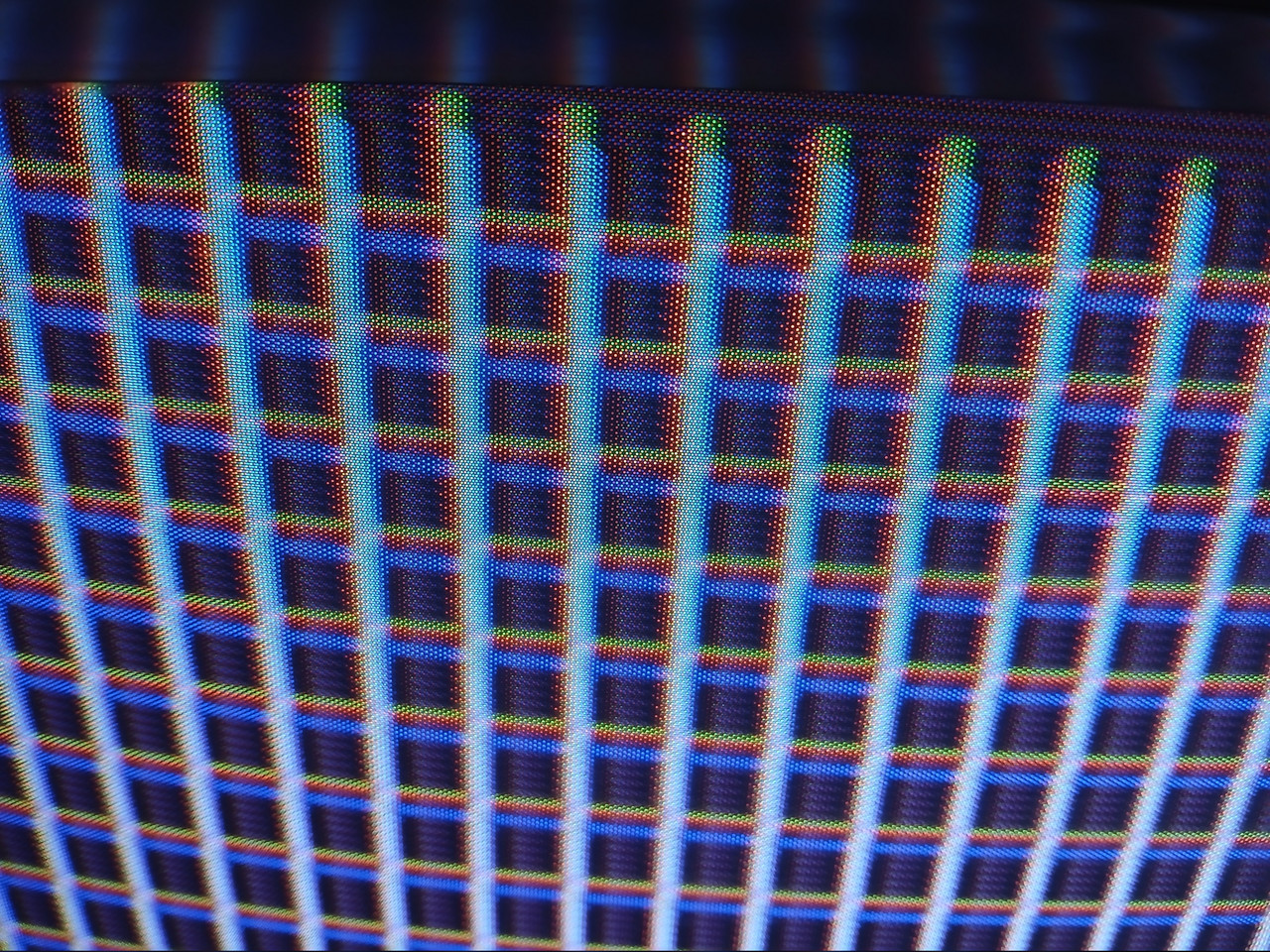
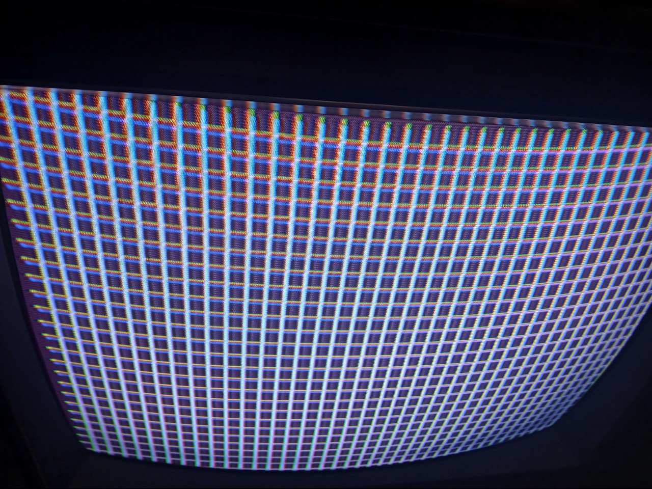
Before we get ahead of ourselves, what im wondering is did the color get affected by the yoke and rings being pushed back toward the socket? I've since moved everything up against the tube and straightened the image but I still have convergence issues as well.


__________________
Genesis does what Nintendon't

Last edited by pac.attack76; 08-15-2026 at 09:05 AM.
Reply With Quote
  #4  
Old 08-15-2026, 10:02 AM
damen's Avatar
damen damen is offline
VideoKarma Member
 
Join Date: Feb 2008
Location: Portland, OR
Posts: 672
Convergence will not cause a lack of color. I would change that module you pictured. Most all of the color circuits are on it.
Reply With Quote
Reply


Thread Tools
Display Modes

Posting Rules
You may not post new threads
You may not post replies
You may not post attachments
You may not edit your posts

BB code is On
Smilies are On
[IMG] code is On
HTML code is Off

Forum Jump


All times are GMT -5. The time now is 04:49 PM.


Powered by vBulletin® Version 3.8.4
Copyright ©2000 - 2026, Jelsoft Enterprises Ltd.
©Copyright 2012 VideoKarma.org, All rights reserved.