
|
|
|
|
|
#1
 07-31-2013, 03:23 PM
|
||||
|
||||
|
Quote:
I ended up testing four flybacks in all. With my Sencore VA62 and YF33, they test between 9 and 10 rings where 10 rings and up is considered good. My Eico 944 showed them all well into the good although the RCA did buzz during testing.  Then, I tried testing the horizontal yoke coils. They showed bad on all three meters. So I pulled a couple nearly identical yokes out of Admiral sets, and they too test bad but about the same as each other. I dug up a NOS yoke from the early 50s and it tested very good on all meters. That leads me to believe that for some reason these meters are not capable of testing very early yokes properly. The yoke currently in the set is an RCA 201D3 and I have a spare 201D1. The D3 has a 56pF cap while the D1 has a 39pF I wonder if that's the only difference ? I figure I'll swap out the caps and give it a try. 
Last edited by bandersen; 08-01-2013 at 05:20 PM. 
|
|
#2
08-06-2013, 05:59 AM
|
||||
|
||||
|
Quote:
I also have a Sencore VA62 -- I'll have to give it a go to see how its done. Carl
__________________
CW 1950 Zenith Porthole - "Lincoln"
|
|
#3
08-06-2013, 06:06 PM
|
||||
|
||||
|
630TS flyback
I just tried a VA62 and a VA62A on my 630TS flyback in circuit. Both read 3 rings with the leads connected to the HOT cap lead and HV rectifier cap lead with the rectifier removed. Not sure how accurate my Heathhkit HV probe is, but it reads about 8KV on the CRT anode with a bright picture. My flyback also had an extra capacitor on it, but I left it off during the re-cap. My picture is a bit narrow so it may benefit from a little added capacitance to get more width.
Dave
|
|
#4
07-31-2013, 08:04 PM
|
||||
|
||||
|
I left the original yoke in the set and replace the flyback with an Admiral. That did the trick
 Glad I tried that before messing around with the yoke. Glad I tried that before messing around with the yoke.I popped in the full sized CRT but couldn't get an image until I tried a PM trap rather than the electromagetic one. I'll have to investigate that further.   After a few minutes of operation, the vertical holds gets very touchy and retrace lines appear. The contrast is pretty touchy too and the sound is poor. Even so it's a big improvement  
Last edited by bandersen; 08-01-2013 at 05:21 PM.
|
|
#5
08-01-2013, 05:16 PM
|
||||
|
||||
|
I finally found the sweet spot for the electromagnetic ion trap
Note that this isn't the CRT that came with the set. It had tested weak so I put it aside in favor of this strong one. I think I'll dig it out later tonight and see what sort of picture it can produce.
|
| Audiokarma |
|
#6
08-02-2013, 02:08 AM
|
||||
|
||||
|
I finally figured out why my fluke 80K-40 HV probe was giving me troubles. The cup the tip screws into had broken loose from the resistor divider!
I soldered it back together and can now say with some certainty that I have 8.5 kV on the CRT anode while the schematic calls for 9kV. 
|
|
#7
08-06-2013, 02:26 AM
|
||||
|
||||
|
I replaced a leaky mica cap in the vertical oscillator and video detector circuits. Also, the 6AU6 final video amp tube was acting weird. After running a while, it would be quite hot and the picture would start fading away. Probably a short was developing in it so it was replaced. All that took care of my vertical hold issue and improved the contrast
The other micas are suspect as well and will be replaced once my order arrives from Mouser in a few days. 
Last edited by bandersen; 08-06-2013 at 02:33 AM.
|
|
#8
08-06-2013, 07:48 PM
|
||||
|
||||
|
Thanks for the info. I get 3 rings in circuit too. I think it's from the yoke loading it down.
Now that the set is running well, I decided to reinstall the original flyback and give it one last try before writing it off. Surprisingly, it works just fine! Around 9.7-10.3 kV depending on the drive control setting. I have no idea why the HV was low earlier  I've replaced, swapped and adjusted so much at this point... I've replaced, swapped and adjusted so much at this point...
|
|
#9
08-07-2013, 05:44 PM
|
||||
|
||||
|
Looking good Bob
 ...Mr Mica Cap strikes again..in some ways I'm kind of glad that NZ TV sets aren't old enough to have those types of micas in amongst the circuit but then again a certain brand of resistor were used in a number of NZ models which are really bad for being very high so that in itself keeps one busy! ...Mr Mica Cap strikes again..in some ways I'm kind of glad that NZ TV sets aren't old enough to have those types of micas in amongst the circuit but then again a certain brand of resistor were used in a number of NZ models which are really bad for being very high so that in itself keeps one busy! Cheers Glen.
__________________
Visit my Vintage TV & Radio Page - http://nzvintagetvradio.blogspot.com/ My YouTube Link - http://www.youtube.com/user/glenz1975?feature=mhsn
|
|
#10
08-09-2013, 08:58 PM
|
||||
|
||||
|
Thanks. At least these micas are fairly easy to get at and are common values.
Here's a test with the original CRT the set came with. It didn't show very good emissions in my tester, but it looks fine to me. 
Last edited by bandersen; 08-09-2013 at 11:01 PM.
|
| Audiokarma |
|
#11
08-28-2013, 09:28 PM
|
||||
|
||||
|
I started going through the alignment procedure tonight. The video IF barely needed any tweaking which didn't surprise me since the picture was quite good already.
The audio IF on the other hand were off quite a bit. Now I have plenty of volume and FM stations aren't leaking in but there is some background hiss. That's after performing the VTVM type alignment. Next, I'll try the visual approach and get an S curve up on the scope. That was all with channel #3. The sound on channel #4 is identical to 3, but the video has snow. Tweaking the channel oscillator helped but nowhere near enough
|
|
#12
08-29-2013, 12:48 PM
|
||||
|
||||
|
Here's what I have for the S curve. Background hiss is unchanged using the OTA converter box I use on the workbench. I tried a different brand and it had much lower volume. I'll try a blonder tongue modulator next.
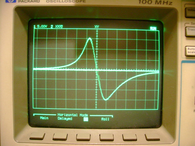 The bandwidth is around 4 MHZ. That's the 2nd from left section where I can make out vertical strips. The last bar is 4.5 MHz.  Vertical linearity needs a slight tweak, but the horizontal looks great. 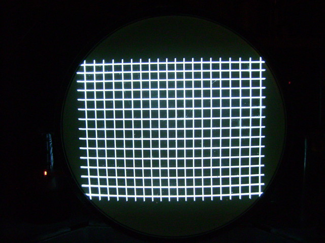
|
|
#13
08-30-2013, 09:16 PM
|
||||
|
||||
|
I decided to cheat a little for the time being and stick this chassis into a cabinet from another set that's in better shape. I'll continue working on the original cabinet when I can.
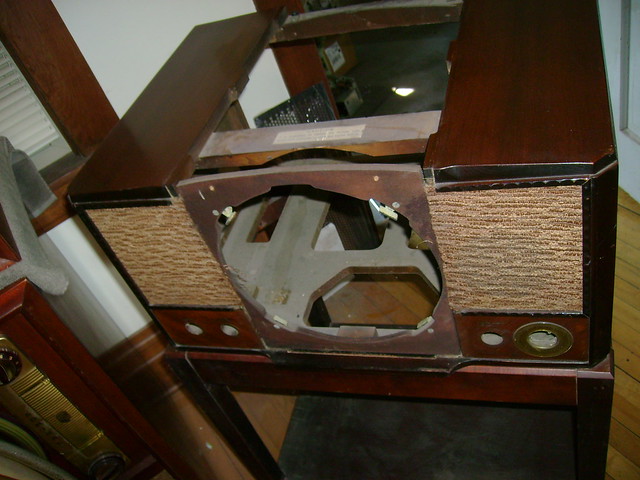 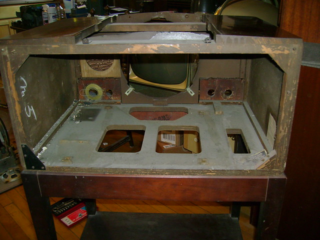 It also a somewhat later production (C61036 vs C29885) that used a plastic channel plate versus a brass one. 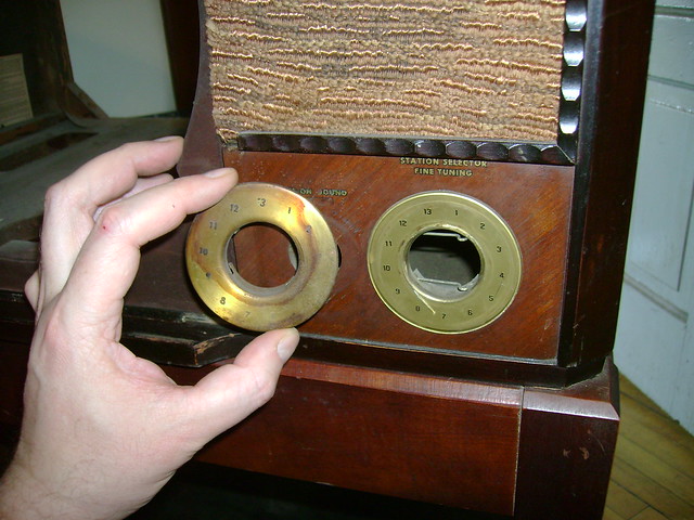 Here's a better look at the stand. 
Last edited by bandersen; 08-30-2013 at 09:22 PM.
|
|
#14
08-31-2013, 12:25 PM
|
|||
|
|||
|
Low volume using DTV converter.
I've had trouble with low volume, even on newer sets, with the Magnavox converters. The other makes seem to be a little better with the volume.
|
|
#15
08-31-2013, 05:13 PM
|
||||
|
||||
|
I too had low volume with a Magnavox converter. An Access DTA1010 was noticeable better. Once I get the set back together, I'll try a Blonder Tongue modulator.
|
| Audiokarma |
 |
|
|




 Hybrid Mode
