
|
|
|
|
|
#1
 03-25-2017, 03:15 PM
|
||||
|
||||
|
Put in the new crystal and things have improved I believe. The oscillator isnt running at the correct frequency as indicated by the lack of color sync. I dont see nearly as much interference anymore. I did blow out the hv cage with compressed air and moved 1 lead that was somewhat close to a solder joint. I'm not sure if I should adjust L127. Fine tuning isnt able to lock the color and neither is the color control. I think I may have to adjust L127 (reactance coil). Still have no red.
__________________
 Admiral C322C2 Regent (Restoring) RCA CTC-7 Pensbury (Restored) RCA CTC-5 Westcott (Restored) CRA CTC--4 Director 21 (Restoring) 
|
|
#2
03-25-2017, 07:03 PM
|
||||
|
||||
|
Do you know if the capacitors are OK
C201 2p C202 120p C209 6.8p C203 .01 C213 270 How about the reactance tube itself (6AN8)? The reactance tube works by amplifying the effect of C201 by the variable gain of the tube. You can check if the oscillator can be pulled by putting, I don't know for sure, but maybe 100pF, from the plate of the reactance tube to ground. If this can pull the oscillator to a lower frequency, and the reactance tube cannot, the problem is in the reactance tube circuit.
|
|
#3
03-25-2017, 08:16 PM
|
||||
|
||||
|
Quote:
__________________
Admiral C322C2 Regent (Restoring) RCA CTC-7 Pensbury (Restored) RCA CTC-5 Westcott (Restored) CRA CTC--4 Director 21 (Restoring)
|
|
#4
03-25-2017, 10:55 PM
|
||||
|
||||
|
Quote:
A crystal for this circuit is cut to parallel resonate with a certain net amount of capacitance. That is, the crystal is operated above its series resonant frequency, and behaves like a large inductor, and is tuned with a small parallel capacitance. If the tank coil is tuned right on frequency, the net capacitance is supplied by the reactance circuit through the 120 pf C202. The tank being on the far side of the 6.8 pF, it takes a large change in the tank tuning to change the total parallel capacitance across the crystal. I don't doubt that it worked, but a more direct way might be to put a small cap (5-10 pF) directly across the crystal. This way, the tank doesn't have to be detuned so far to get the required net capacitance. Adding capacitance across the tank means you are detuning it from exact parallel resonance to be capacitive when the oscillator is locked, while I think it is really intended to be more or less exactly parallel resonant for oscillator operation. Different TV manufacturers may have specified different parallel capacitances, for nominal parallel resonance of the crystal. (probably between 18 pF for Zenith [if i recall correctly] and possibly higher values [maybe up to 32 pf but probably in the 20s] for other manufacturers). So, it's possible the crystal you got is not cut for the net capacitance in this chassis, and some more capacitance is needed. This should come from the reactance circuit, not the tank circuit, which is why you tune the reactance coil to zero beat the oscillator.
|
|
#5
04-01-2017, 04:50 PM
|
||||
|
||||
|
I tacked on a 5 pf cap across the crystal and I can almost get the oscillator to run at the right frequency. It still wont lock even after 20 turns on the reactance coil. Here is what I could get (note the bars rapidly change color every second but I no longer have the barber pole rainbow.)
__________________
Admiral C322C2 Regent (Restoring) RCA CTC-7 Pensbury (Restored) RCA CTC-5 Westcott (Restored) CRA CTC--4 Director 21 (Restoring)
|
| Audiokarma |
|
#6
04-01-2017, 06:59 PM
|
||||
|
||||
|
Ok, now you have a chance to find out what part of the loop is dead.
If you have a scope, connect to the top of C198 (4700). If you don't have a scope, connect a DC voltmeter there. Center the AFC balance control. Tune the oscillator so the color cycles through slowly, and you should see the voltage cycle slowly also, as the phase detector cycles through its full range. I don't know what the normal range is, but it should be at least a few volts variation, maybe +/- 10 from nominal zero at most? [Note that the schematic says the nominal control voltage on the grid of the reactance tube is zero volts, so the phase detector output should vary +/- around zero when it is out of lock.] If there is no variation, then either the burst keyer or the phase detector may be dead. If there is a variation, then your problem is still in the reactance tube or oscillator. Last edited by old_tv_nut; 04-01-2017 at 07:04 PM.
|
|
#7
04-03-2017, 04:03 PM
|
||||
|
||||
|
I checked voltages and waveforms at C198 which is a .01 in this case since I have the early production run of the chassis. I got about 10 volts on the top side of the .01 and 0 volts at the ground side. I didnt see any variation in voltage when adjusting the reactance coil (provided I adjusted the right coil). Here is the waveform I observed at the top side of this cap. Please note that all these measurements were taken with the chassis on the workbench. So no HV or connection to the CRT at all. Here is what I found.
__________________
Admiral C322C2 Regent (Restoring) RCA CTC-7 Pensbury (Restored) RCA CTC-5 Westcott (Restored) CRA CTC--4 Director 21 (Restoring)
|
|
#8
04-03-2017, 05:59 PM
|
||||
|
||||
|
Forget the HV, but is the horizontal running on the workbench? It has to be running in order to get a burst gate pulse. No burst gate, nothing gets to the phase detector, so impossible to tell what's wrong or not.
Also, is the scope set for DC coupling? The variation you are looking for is slow, same rate as the color changing a few times per second, so with your high speed scope setting and DC coupling, you would expect the trace to go up and down a few times a second, in sync with the color phase changing. If the scope is set to AC coupling, you won't see such a slow variation at all. One more thing - if the color is changing rapidly, the voltmeter may not respond in time, that's why the scope is preferred. Last edited by old_tv_nut; 04-03-2017 at 06:04 PM.
|
|
#9
04-03-2017, 06:26 PM
|
||||
|
||||
|
Quote:
__________________
Admiral C322C2 Regent (Restoring) RCA CTC-7 Pensbury (Restored) RCA CTC-5 Westcott (Restored) CRA CTC--4 Director 21 (Restoring)
|
|
#10
04-03-2017, 06:41 PM
|
||||
|
||||
|
Got an analog VOM with a d'arsonval meter? That ought to capture the variation.
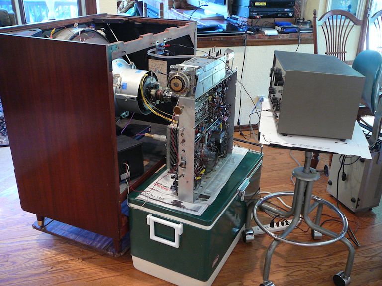
Dirty secret to taking under-chassis measurements with the chassis in the cabinet: get some clip leads connect one end of a lead to a relevant test point and run the other out from under the chassis to your meter probe and slide the chassis back in the cabinet....That method has saved my bacon on sweep and boost troubleshooting a few times. Also table model CTC-4s have enough harness length (except maybe HV, but that can be addressed) that you can set the chassis up on the floor behind the cabinet with all the under-chassis exposed...For a console like yours if you can find a sturdy box or some such as high off the ground as the chassis shelf then you should be able to pull it up to the back of the set place the chassis on it and make everything reach/accessible.
__________________
Tom C. Zenith: The quality stays in EVEN after the name falls off! What I want. --> http://www.videokarma.org/showpost.p...62&postcount=4 Last edited by Electronic M; 04-03-2017 at 06:46 PM.
|
| Audiokarma |
|
#11
04-03-2017, 06:46 PM
|
||||
|
||||
|
Quote:
__________________
Admiral C322C2 Regent (Restoring) RCA CTC-7 Pensbury (Restored) RCA CTC-5 Westcott (Restored) CRA CTC--4 Director 21 (Restoring)
|
|
#12
04-04-2017, 04:25 PM
|
||||
|
||||
|
Quote:
 Phil Nelson Phil's Old Radios http://antiqueradio.org/index.html
|
|
#15
04-05-2017, 04:44 PM
|
||||
|
||||
|
I do the same thing, but I use a sturdy stool instead of a cooler. Makes everything so much easier for sure!
__________________
Admiral C322C2 Regent (Restoring) RCA CTC-7 Pensbury (Restored) RCA CTC-5 Westcott (Restored) CRA CTC--4 Director 21 (Restoring)
|
| Audiokarma |
 |
|
|


 Hybrid Mode
