
|
|
|
#1
 03-23-2018, 06:03 AM
|
||||
|
||||
|
Ts4d Motorola
There is a component marked cr-1 it's rectangular with 4 legs and is mounted between the audio amp and output tubes. Is this a dual capacitor or a resistor array, I can't find a schematic with the parts list to identify it. Still trying to find out what's wrong with the audio why it's got a hum. From what I found is that the ts4d was the only chassis that had this component.

|
|
#2
03-23-2018, 07:17 AM
|
|||
|
|||
|
Timmy,
That CR-1 is a capacitor- resistor array as you suspect. The parts are listed as 4 individual components ; C-145 a 0.1 mf, C-144 a 250mmf, R-120 a 250k, and R-121 a 500k . A company named Centralab may have produced that array . If you suspect a faulty component then, you may have to make up your own replacement array. Ed Last edited by EdKozk2; 03-23-2018 at 09:24 PM.
|
|
#3
03-23-2018, 08:49 AM
|
||||
|
||||
|
We'll unfortunately moyers says there is no listing by cr-1 in centralab so either I make it up or maybe find a SAMs with the parts listing with numbers that maybe moyers can use to maybe find one. Got a hum in the audio and can't find anything wrong so I'm at this array maybe possibly it's bad.
|
|
#4
03-23-2018, 10:10 AM
|
||||
|
||||
|
Is it original to the set ? I don't recall ever seeing a part like that in any TS-4 chassis revision
|
|
#5
03-23-2018, 12:11 PM
|
||||
|
||||
|
Quote:
|
| Audiokarma |
|
#6
03-23-2018, 04:29 PM
|
||||
|
||||
|
Download the original Motorola service info from the ETF.
http://www.earlytelevision.org/pdf/m...svc_manual.pdf It has detailed service info on the early chassis revisions. Here's a portion of the TS-4D showing the couplate values. 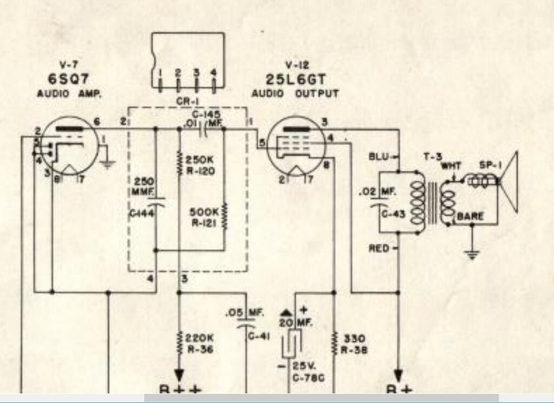
|
|
#7
03-23-2018, 07:05 PM
|
||||
|
||||
|
Don't look for the exact part, make a new one out of good new parts...Original couplates can be a nightmare to source, and if the original is bad there is no guarantee NOS will be good.
__________________
Tom C. Zenith: The quality stays in EVEN after the name falls off! What I want. --> http://www.videokarma.org/showpost.p...62&postcount=4
|
|
#8
03-24-2018, 04:53 AM
|
||||
|
||||
|
Well I really don't know if this couplate is even bad since the audio is loud and clear just has the hum with it. I can't find a possible way AC can get into to audio via a bad couplate. If AC was on the + or - and it's affecting the audio with a hum then it should affect other areas of the set like the picture quality , maybe hum bars , but there's nothing.
Last edited by timmy; 03-24-2018 at 06:22 AM.
|
|
#9
03-24-2018, 01:10 PM
|
||||
|
||||
|
This is where the method of *Process Of Elimination* comes in handy. What i would suggest is to disconnect what is connected to pin 2 on V7 (6SQ7) & then power up the set & see if you still have hum. there should be silence. if the hum stops, You can eliminate the audio amp & output stage as being the problem. the problem then, would be somewhere upstream in the I.F. or in the audio detector stages. If the hum is still there, there is a problem with the source voltage from the B++ rail that supplies the audio amp stage.
Are you sure that the hum is a 60 cycle ripple, & not a buzz caused by sync pulses?
|
|
#10
03-24-2018, 02:12 PM
|
||||
|
||||
|
Quote:
|
| Audiokarma |
|
#11
03-24-2018, 07:23 PM
|
||||
|
||||
|
Quote:
the only things i can think of is there is a filament to cathode leakage on ether of the 6SQ7 or the audio output tube, or high ripple on ether the B+ or B++ sources. it also could be originating at the volume control itself (broken ground connection). if you had a scope, you could trace the audio signal path to the point where the AC ripple is coming from.
|
|
#12
03-26-2018, 11:48 AM
|
||||
|
||||
|
Quote:
|
|
#13
03-26-2018, 12:47 PM
|
||||
|
||||
|
Quote:
the reason why i ask this is because the grounding for the entire audio is isolated from the chassis & connected to the B- rail. If you connected the negative of that capacitor to chassis, that could be the problem. regarding the volume control, if the ground connection on the wafer in the control is open, it can cause the same problem. you need to disconnect the leads off the volume pot & check for end to end continuity, as well as continuity between the wiper contact as it is moved from one end to the other. i have seem many bad pots cause this problem.
|
|
#14
03-26-2018, 01:21 PM
|
||||
|
||||
|
Quote:
|
|
#15
03-26-2018, 01:32 PM
|
||||
|
||||
|
Ok the volume control checks out, wiper to end does vary the way it supposed to. So now still at dead end, I even tried other diodes thinking one may be leaky but no luck there and I also paralled every cap still no luck still hums. The Motorola Manuel showed reasons for a hum and I checked that out still no luck. When I first got the set I had to tweek the IF for a clear pic and sound and the Manuel says if the oscillator is adjusted to high it's considered to be overloading and the audio would get a 60 hz hum carried along the verticle circuit, strange, hmmm. Checked around the verticle to no avail. What I also tried was I turned the 3 adjustments L17 ,L19 , L27 4 turns cw then 4 cww to see if that made a difference in the hum if that were the reason but I never did turn them a lot in the beginning.
Last edited by timmy; 03-26-2018 at 01:41 PM.
|
| Audiokarma |
 |
|
|


 Linear Mode

