
|
|
|
#271
 02-05-2015, 11:45 AM
|
||||
|
||||
|
I was looking at the 7watt resistor I removed, and I noticed it's a 17k resistor and not a 13k, that explains the 17k reading on that one, but in the sams, it's suppose to be a 13k in that place.. Not sure if that was a production change, or if someone changed it out to a higher ko resistor..
__________________
Looking for an all tube or hybrid color TV set from the late 1960s, early 1970s that's in a steal cabinet.. 
|
|
#272
02-11-2015, 06:54 PM
|
||||
|
||||
|
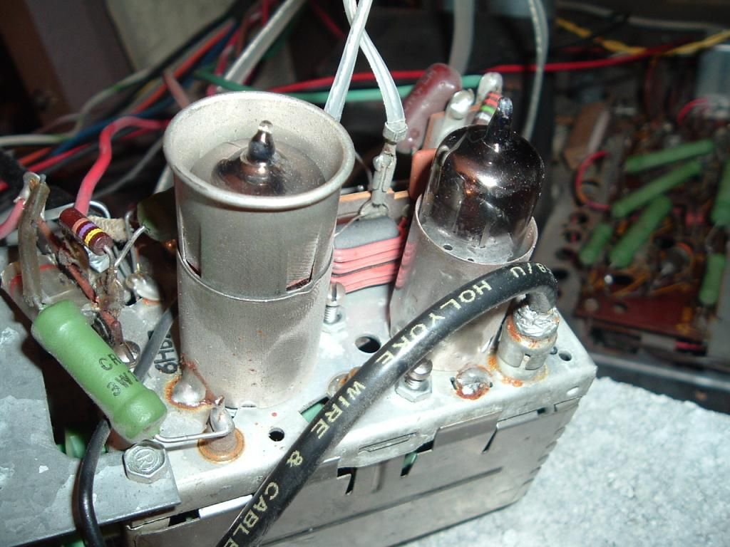
I received tubes for the tuner.. Made no difference as for UHF or anything else (No Change).. When changing the VHF tuner and when I go past channel 2 the program comes in as clear on that channel as channel 3.. So using a signal source that's set to channel 3 comes in perfect on this TV on both 2 and 3 channels.. Is that an issue, or should I not worry about that? I don't see a switch anywhere to turn UHF on or off, and the black coax cord with the RCA jacks on each side is connected to each, and there is also a red wire that looks to be the B+ connecting in between VHF and UHF tuners.. I did check all the resistors that are pictured near the tubes, and all check in range, there are two caps in that area that are also pictured.. I haven't checked them, and really have no reason to seeing how all the orange drops that I replaced were good.. There is also that aluminum looking cap with a red line around it (Also pictured).. What also should I do?
__________________
Looking for an all tube or hybrid color TV set from the late 1960s, early 1970s that's in a steal cabinet.. Last edited by tvcollector; 02-11-2015 at 07:09 PM.
|
|
#273
02-12-2015, 08:21 AM
|
||||
|
||||
|
Is it the piece with the red wires wrapped around it between the tubes? If so, that is the tuner balun. It converts 300 ohm balanced back to 72 ohm unbalanced so the tuner can use the signal. Usually the only time they fail is lightning and it is very obvious as they get burned up.
|
|
#274
02-12-2015, 09:08 AM
|
|||
|
|||
|
Quote:
|
|
#275
02-12-2015, 05:21 PM
|
||||
|
||||
|
Trying to follow the sams for the tuner, Sams lists two different VHF tuners. Model ET86X221 and ET86X248.. Mine is the ET86X248, but sams is showing a tuner that's alot different. I have no idea what that aluminum cap is, and the .033 cap that's in the picture, which looks to be cap 207, in the sams under the VHF tuner parts list, the cap that sams points to is a .001 that is soldered into that slug.. Sams is showing caps in areas where there isn't any on the tuner, same as resistors, and shows no cap rated .033 in the parts list at all.. I don't seem to see anykind of jumper anywhere also..
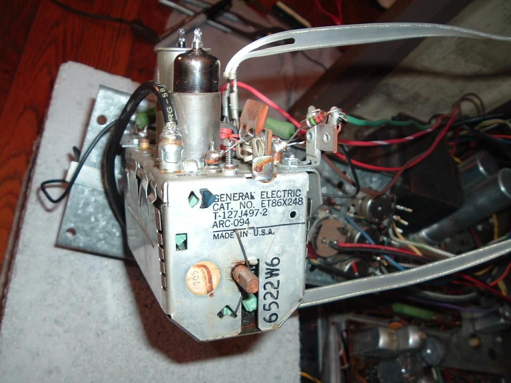 First pic here shows the red wire which looks to be the B+ wire I was talking about 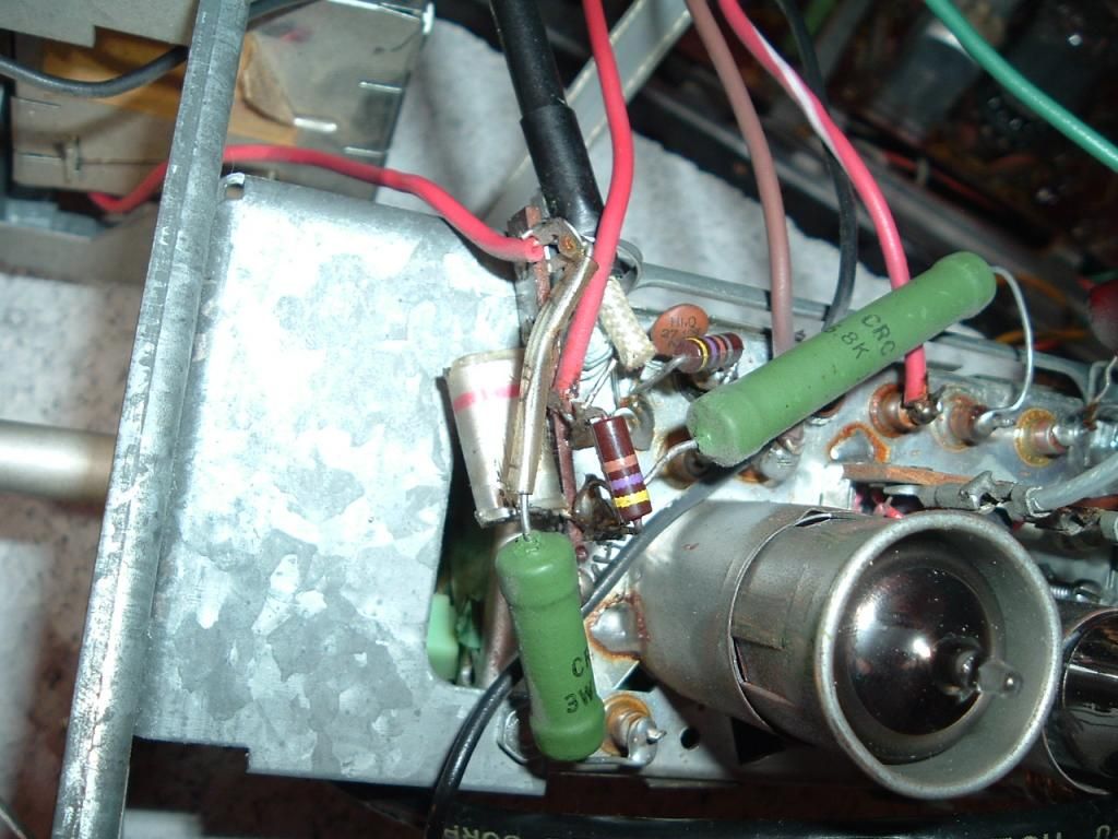 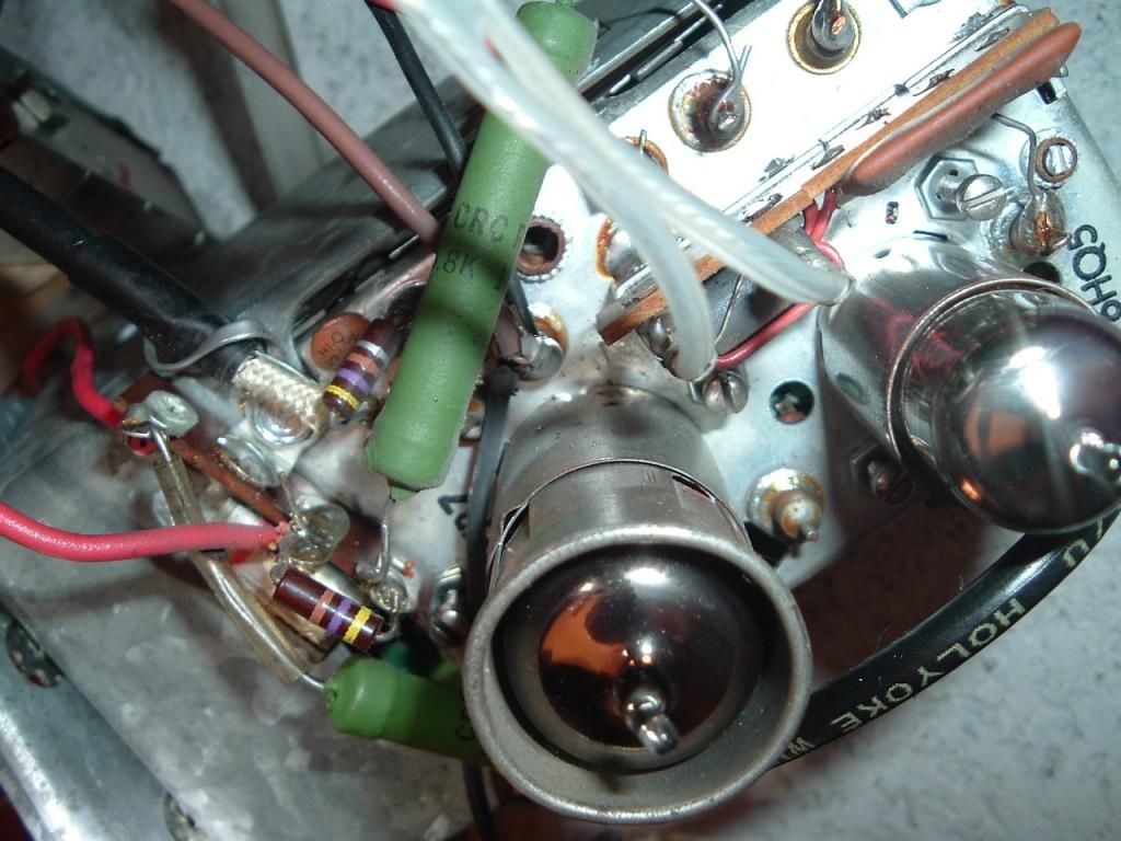 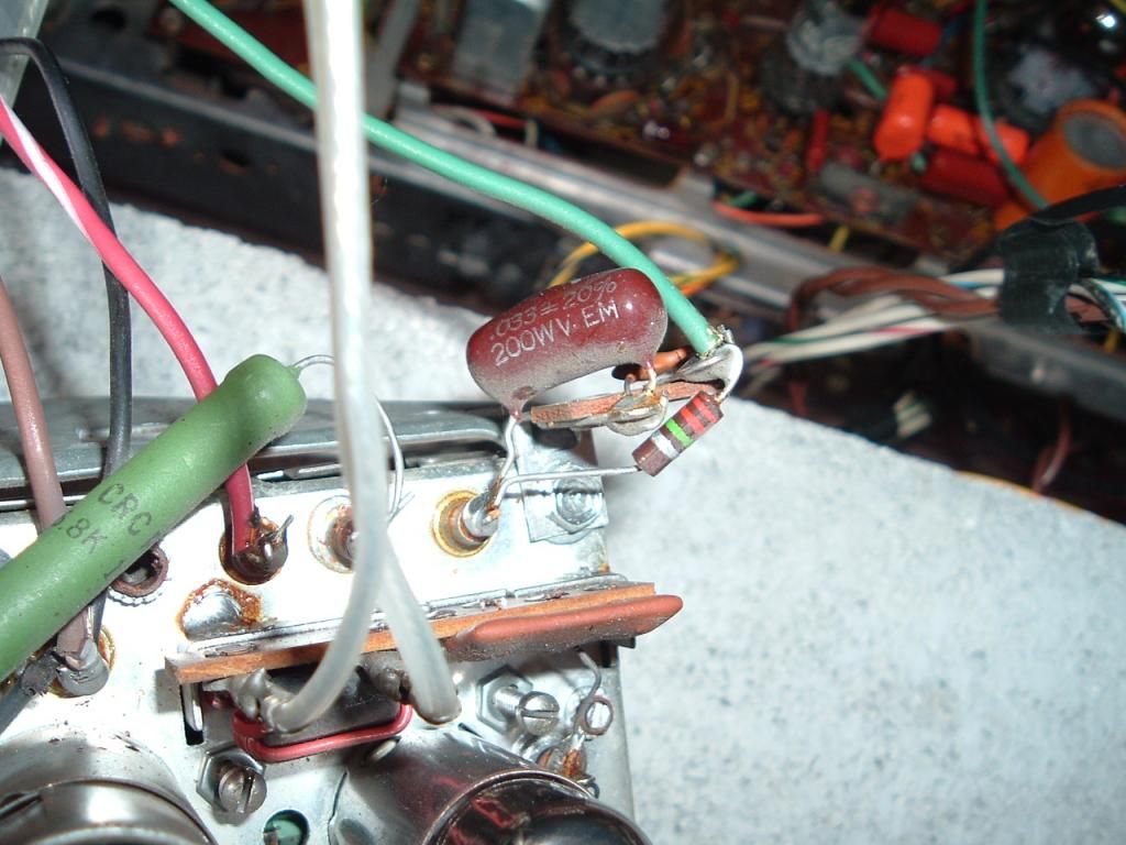
__________________
Looking for an all tube or hybrid color TV set from the late 1960s, early 1970s that's in a steal cabinet.. Last edited by tvcollector; 02-12-2015 at 05:53 PM.
|
| Audiokarma |
|
#276
02-12-2015, 07:44 PM
|
||||
|
||||
|
Was able to bend the aluminum cap slightly and get under it with the camera.. Looks to be 047 20%.. Can't tell the voltage..
Update: Found out it's rated at 400v.. I have a 600v on hand of that value and changed it out.. No difference in performance.. I can almost guarantee you the orange drop is fine.. 
__________________
Looking for an all tube or hybrid color TV set from the late 1960s, early 1970s that's in a steal cabinet.. Last edited by tvcollector; 02-12-2015 at 09:31 PM.
|
|
#277
02-13-2015, 08:07 AM
|
||||
|
||||
|
A few notes on tuners.
Most tuners will normally tune adjacent channels if you turn the fine tune enuf times. Most common problem on UHF in GE's is the coax link, they didnt solder the center pin ! You can plug a tuner subber into the UHF IF cable to test the VHF tuner for UHF ops. When you put the set on UHF it switches on B+ ( 12-24 VDC ) for the UHF tuner. It also turns off the VHF osc stage & turns the RF amp & mixer stages into two more IF stages. Also it looks like it has a tuner cleaning pad. This should be removed. They dry out & break up & make a mess. Pop the cover off by light pressing of the claws on each side of the tuner. 73 Zeno 
|
|
#278
02-13-2015, 08:48 AM
|
|||
|
|||
|
Quote:

|
|
#279
02-13-2015, 11:44 AM
|
||||
|
||||
|
Looks like what ever padding was there was removed from previous owners, there's slight sign of it being there, as there is slight residue.. I unplugged coax cable and checked for continuity putting the probe of meter under the coil where middle pin goes into, and other side unhooked from UHF tuner and to middle pin and there is continuity.. I didn't open the UHF tuner and test the other way around yet.. So would I be able to test b+ by switching to UHF position, and the probe of meter to the red wire and black to tuner chassis and get the voltage readings you mentioned?
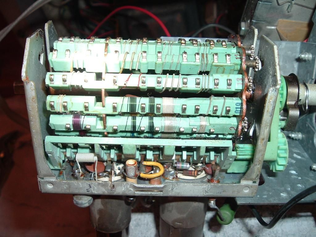
__________________
Looking for an all tube or hybrid color TV set from the late 1960s, early 1970s that's in a steal cabinet.. Last edited by tvcollector; 02-13-2015 at 11:47 AM.
|
|
#280
02-13-2015, 08:43 PM
|
||||
|
||||
|
Hooked my volt meter up to the hot wire running to the UHF tuner and other to tuner ground.. As soon as I go to channel U for UHF, the meter goes right into OL and beeps fast in DC mode..
__________________
Looking for an all tube or hybrid color TV set from the late 1960s, early 1970s that's in a steal cabinet..
|
| Audiokarma |
|
#281
02-15-2015, 01:52 PM
|
||||
|
||||
|
Quote:
main chassis. Resolder the IF link anyways, they just crimped most of them. Two other UHF problems are: on some cheap GE U tuners the drive would go. Also on any UHF tuner there are U shaped grounds along the shaft. We used to pull them, bend them a little & clean things real good. Then we discovered that a few drops of WD40 would clean most of them without all the time & risk involved. 73 Zeno
|
|
#282
02-15-2015, 06:16 PM
|
||||
|
||||
|
I measured by hooking the ground to main chassis and I'm getting 9.5 VDC..
__________________
Looking for an all tube or hybrid color TV set from the late 1960s, early 1970s that's in a steal cabinet..
|
|
#283
02-16-2015, 07:02 PM
|
||||
|
||||
|
Just located the tuner B+ info on the main schematic.. The voltage should be 19.5 VDC.. I'm getting slightly less than half.. Don't know where to go from there..
__________________
Looking for an all tube or hybrid color TV set from the late 1960s, early 1970s that's in a steal cabinet..
|
 |
|
|




 Linear Mode

