
|
|
|
#16
 03-31-2012, 10:05 PM
|
||||
|
||||
|
I cant afford any of those big huge caps so would it be fesable to paralell 8 10µF caps to get the 80 mfd cap i know it would be rather clunky bu would it work?

|
|
#17
03-31-2012, 10:56 PM
|
||||
|
||||
|
also, i have never been good at reading the black beuaaty caps and there is one that looks like it will have a large rating but im unshure i get 15 mfd at 1,000 v bu could someone please check it for me with the foil facing my left it goes brown green yellow purple blank space and yellow agan.
|
|
#18
03-31-2012, 11:25 PM
|
||||
|
||||
|
If you get the schematic, you can look up the values rather than guess or try to read them off the old caps.
The article at http://antiqueradio.org/recap.htm has a section on identifying capacitor values, including this chart: 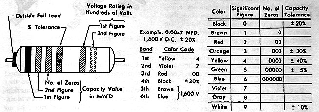 I believe brown-green-yellow would be .15 mfd. That would be a reasonable value for that type of capacitor. As noted in the article, certain kinds of caps usually have values in a certain range. 15 mfd would be reasonable for an electrolytic, but not a bumblebee (paper) cap. Wiring eight electrolytics in parallel sounds ugly, although it might work. Is it really that much cheaper to use eight caps in place of one? Phil Nelson
|
|
#19
03-31-2012, 11:29 PM
|
||||
|
||||
|
That seems to be 0.15uF at 400 volts to me, but others may know better.
__________________
Chris Quote from another forum: "(Antique TV collecting) always seemed to me to be a fringe hobby that only weirdos did."
|
|
#20
03-31-2012, 11:30 PM
|
||||
|
||||
|
Oops, double post. Ironically, I was double-checking my reading on your capacitor page, Phil!
__________________
Chris Quote from another forum: "(Antique TV collecting) always seemed to me to be a fringe hobby that only weirdos did."
|
| Audiokarma |
|
#21
03-31-2012, 11:31 PM
|
||||
|
||||
|
.15 sounds much better. doing the paralell thing i can replace all of the filter caps for under 7.00 and if it dosent work i have several projects going on right now that need a few 10's. This better work!
I have all of my parts picked out on mouser and im going to order them tommrow morning!
|
|
#22
04-01-2012, 09:08 AM
|
||||
|
||||
|
Not sure on this chassis, but pay attention to what the B+ Boost cap is and how it is wired in the circuit. Most times it will be tied to ground or in my case it "floats" between the B+ and B+ Boost sources. This will dictate a non-polorized application! However, good luck in trying to find a 10uf@400v non-polar!!
Although some may understandably cringe, you can tie two electrolytics together in series and connect the negatives together. For my 10uf application, I used two 22uf@450v as capacitance decreases in series, getting the desired value. This is "acceptable" but it's always best to use designed non-polars if possible. My Howard Sams in the parts description lists this as an alternative also. I've run the set considerably and the cap(s) run cool and work as intended. As for that .15@400v cap, it's got boosted/pulsed B+ on it and ties to the plate of the Damper Tube. IMO I would use a good quality orange drop and step up the voltage rating to 600V. I've got a good stock of these and if money is an issue I'd be glad to send you one!
|
|
#23
04-01-2012, 10:55 PM
|
||||
|
||||
|
Where can i buy the decals on the top that say horozontal vertical brightness contrast ect? I looked on all of the sites like antique radio supply ect but no noe had them.
|
|
#24
04-02-2012, 12:19 AM
|
||||
|
||||
|
I've paralleled 4x 22MFD to replace an 80MFD cap before (the extra 8 MFD really did not matter in the circuit I used it in) and all was fine. I've paralleled 5x 22 to make up replacements for 100 MFD doubler caps before as well. The key is to mind the polarity on lytics.
__________________
Tom C. Zenith: The quality stays in EVEN after the name falls off! What I want. --> http://www.videokarma.org/showpost.p...62&postcount=4
|
|
#25
04-03-2012, 06:21 PM
|
||||
|
||||
|
can a .068 paper cap be subed for a .058 mouser sent me the wrong capacitor it says i ordered .068 on the bag buta .058 is on the capacitor?
|
| Audiokarma |
|
#26
04-03-2012, 06:50 PM
|
||||
|
||||
|
It is probably close enough, yes. .058 is an unusual value; if you have trouble with that circuit later, you could use a .047 and .01 in parallel instead.
__________________
Chris Quote from another forum: "(Antique TV collecting) always seemed to me to be a fringe hobby that only weirdos did."
|
|
#27
04-03-2012, 07:00 PM
|
||||
|
||||
|
thanks i didnot want to blow it up or something.
|
|
#28
04-03-2012, 08:20 PM
|
||||
|
||||
|
ok got all of the caps in and nothing no raster there is a buzzing sound tht goes up and down wiht the volume control and the tubes seem to be glowing unusually bright.
|
|
#29
04-03-2012, 08:44 PM
|
||||
|
||||
|
I powered it up in a dark room today to see of i could see any sparks anywhere and inside of the 5a4ga rectifyer tube there are sparks flying around inside it and it got really hot really fast! Does anyone have any clues? guess i have to get a schamatic now....
|
|
#30
04-03-2012, 09:57 PM
|
||||
|
||||
|
Quote:
Do not power up the TV any more until you have double-checked all of your capacitor replacements against the schematic. Make sure that the polarity of the new electrolytics is correct and that the old electrolytics are disconnected. The new electrolytics should not be wired in parallel with the old ones. Phil Nelson
|
| Audiokarma |
 |
|
|








 Linear Mode

