
|
|
|
#16
 02-22-2014, 10:09 PM
|
||||
|
||||
|
I believe the rear horizontal hold control is basically a coarse frequency adjuster and the front one is a fine adjuster. If both are working, you would set the rear one so that you have good horizontal stability with the front control set at the center of its travel. After that, minor adjustments can be made with the front control alone. In other words, the rear (coarse) control gets you in the right ballpark, and you make everyday adjustments with the front control. Your service manual should explain all of that, or at least give brief instructions for setting these controls.
If the rear control is a potentiometer, the simple repair is to replace it with one of the same value. While you're waiting for the new pot to arrive in the mail, I suppose you could experiment with substituting a fixed resistor for that control -- trying different likely values until you find one that gives you a stable picture. That's not a good long-term solution (there is a reason why the designers used a pot there instead of a fixed resistor), but at least you could watch the TV in the meantime. If the rear control is an adjustable coil, maybe not so easy to find a sub. Moyer is sometimes able to supply vintage TV parts: http://www.moyerelectronics.com/Depa...-TV-Parts.aspx Just my $0.02. Phil Nelson Phil's Old Radios http://antiqueradio.org/index.html 
|
|
#18
04-13-2014, 10:03 PM
|
||||
|
||||
|
I took another look at this project today. I wrote down all of the values of the micamold style caps to order replacements. These are all very small value, most around 100pf.
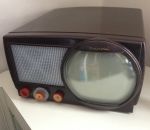
The issue I can't figure out is a severe linearity distortion on the left hand side of the screen. See attached. There is even a brightness variance on this band of distortion. All paper and electro caps have been replaced. All I can think to do next is replace the micamold caps. The horizontal linearity control works, but it does not change the distortion at all.
|
|
#19
04-13-2014, 11:10 PM
|
||||
|
||||
|
These sets have a lot of domino-style caps in the sweep and sync sections. I was just working on one today, and it had jumpy sync, so I bit the bullet and just replaced all the mica and mica-like caps in the board near the sweep circuitry (I left the micas in the RF and IF sections, which I generally find don't need attention nearly as often). This solved my problem completely. You may simply want to do the same thing in your set, at least for all the mica caps directly involved in the horizontal sweep. There are probably something like 8 of them in that circuitry. Overall, I replaced something like 17 (!) mica and mica-like caps today in the entire sweep and sync sections.
Note that not all of the mica-like caps in the sweep section are low pF. I replaced a number in the 1000 pF, 3900 pF, and 6800 pF range as well (these are the larger rectangular caps).
|
|
#21
04-13-2014, 11:31 PM
|
||||
|
||||
|
Thanks guys, looks like that's what I will do.
I must be reading these cap values wrong as I found nothing anywhere near that high in capacitance. I got ahold of the photofact hoping that would help to ID the values, only to find the chassis in the pictures has different components all over the place.
|
|
#22
04-13-2014, 11:59 PM
|
||||
|
||||
|
Check the big letter stamped on the front of your chassis. The various Rider schematics for the 800 series can be found here: http://www.earlytelevision.org/tv_sc...s_postwar.html . There are quite a few variants, but perhaps you'll be able to find a schematic that matches your set pretty well. Mine is stamped "W" which matches the Sams schematic pretty well.
|
|
#24
04-14-2014, 08:36 PM
|
||||
|
||||
|
Instead of going off the color codes on the capacitors and going by the schematic I have a list of approx 14 or so caps to replace in the horizontal sweep area, and the values seem much more reasonable.
Hopefully get back to this one by the weekend or early next week when the caps come in.
|
|
#25
06-18-2014, 11:40 AM
|
||||
|
||||
|
Late update, but I finally got around to replacing all the mica caps in the horizontal section. No change to the set's behavior. The stretching on the left hand side is still the same. Also the H and V are relatively unstable even with a very strong signal.
Any other ideas where I can look? All tubes are good, all paper, electrolytic, and horz mica caps have been replaced. Is this a grounding issue? What about the mica cap on the yoke?
|
| Audiokarma |
|
#26
06-19-2014, 12:18 AM
|
||||
|
||||
|
Have you tried adjusting the horizontal drive level ?
|
|
#29
06-22-2014, 10:56 PM
|
||||
|
||||
|
Could be if there's a shorted turn. It's rather odd the the drive control has no effect. It should have a very noticeable effect in the linearity and brightness as it controls how much signal gets to the horizontal output tube.
|
|
#30
07-10-2014, 11:28 PM
|
||||
|
||||
|
Got the coil from Moyers for $10
 , but unfortunately it wasn't the issue, the old coil ended up testing good out of circuit, but bad in circuit. I tried the new coil anyway but TV has the same issue. , but unfortunately it wasn't the issue, the old coil ended up testing good out of circuit, but bad in circuit. I tried the new coil anyway but TV has the same issue.
|
| Audiokarma |
 |
|
|




 Linear Mode

