
|
|
|
#16
 03-12-2014, 06:58 PM
|
||||
|
||||
|
Quote:
Quote:
you may need to examine that "brightener" to make sure that it is not a 1:1 ratio isolation transformer. that tube may have had a intermittant fil to cathode short. 
|
|
#17
03-12-2014, 07:10 PM
|
||||
|
||||
|
Quote:
i would love to have this set to restore. sets like these are non-existant in this area. That is a nice find.
|
|
#18
03-12-2014, 07:14 PM
|
||||
|
||||
|
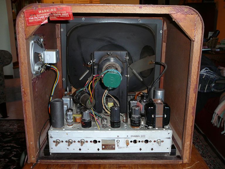
That power transformer looks a little too small to do anything other than feed heaters. And I don't see a 5U4. Just be sure it's not a hot chassis. Or take the appropriate care if it is.
__________________

|
|
#19
03-12-2014, 08:00 PM
|
||||
|
||||
|
No rectifier tube.
Phil Nelson 
|
|
#20
03-12-2014, 09:14 PM
|
|||
|
|||
|
Quote:

|
| Audiokarma |
|
#21
03-12-2014, 09:31 PM
|
||||
|
||||
|
I think it looks great! three IF stages, not two! Not as cheap as it could be. Insides look clean! Show us the chassis underneath when you can!
|
|
#22
03-12-2014, 10:31 PM
|
||||
|
||||
|
I replaced a couple of bad tubes and ran it up to about 100 volts on the variac (hey -- do what I say, not what I do
 ), when what to my wondering eyes should appear, but a bright green glow in the CRT neck. ), when what to my wondering eyes should appear, but a bright green glow in the CRT neck.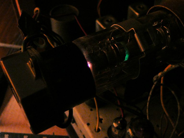 What the heck? The glow comes from what looks like some kind of schmutz on the tube element. 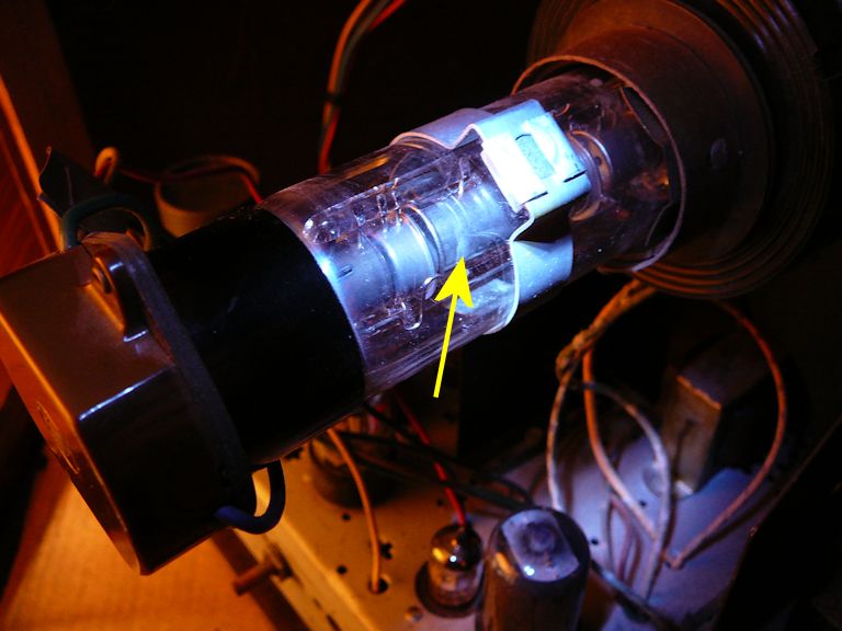 This is without using the brightener (or should I say Britener?). 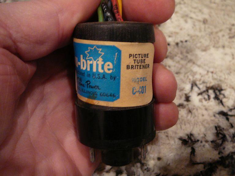 At roughly 100V the TV produces fine audio, which is mildly encouraging. The ion trap magnet was originally far back against the tube base. I slid it forward out of curiosity and found that it has a slight effect on the green glow. Never having seen a green glow outside of a magic eye tube -- this looks exactly the same shade, by the way -- I am most curious. Phil Nelson
|
|
#23
03-12-2014, 11:28 PM
|
||||
|
||||
|
I seem to recall reading something about CRT makers using some type of marker for lining up the Ion trap, since this seems to be directly under the trap I wonder if that's what this is?
Obviously not gas because that would be purple and between the elements, this almost looks like it's something (phosphor?) applied to the outside of that part.
|
|
#24
03-12-2014, 11:39 PM
|
||||
|
||||
|
It definitely looks like a patch (or maybe stripe?) of something on the outside of that element. Possibly the same kind of green phosphor used in magic eye tubes or green CRTs?
For what it's worth (maybe nothing), the ion trap was originally not in that position. It was way back against the tube base and rotated about 30 degrees. Of course, someone might have monkeyed with it before, although the set doesn't show any obvious signs of tampering and the cover does have an AC interlock. Phil Nelson
|
|
#25
03-12-2014, 11:40 PM
|
||||
|
||||
|
I'm guessing that green p-1 phosphor has been applied to the outside of the anode barrel to provide an indication of proper ion trap adjustment... minimize the scattered electrons = minimized green glow = max beam current down the gun to the screen. Just a WAG, however.
jr
|
| Audiokarma |
|
#26
03-13-2014, 12:01 AM
|
||||
|
||||
|
Quote:
Maybe it's peculiar to this one brand, or rebuilder? Curious how it can work being on the outside of the metal cylinder, unless it works by the cylinder becoming charged when the beam is hitting it instead of going down the center?
|
|
#27
03-13-2014, 12:04 AM
|
||||
|
||||
|
Phil, you never said if you got a raster or not?
|
|
#28
03-13-2014, 12:51 AM
|
||||
|
||||
|
Found this in a Rauland patent for a electrostatic focus CRT:
Quote:
jr
|
|
#29
03-13-2014, 01:10 AM
|
||||
|
||||
|
Wow, that's interesting. I wonder if this could be a Rauland tube? I don't see any labeling on the base or what's visible of the neck.
The first time I tried the ion trap, I could clearly see the glow brighten or darken at various positions. (One practical drawback of this scheme is that the room needs to be nearly pitch black to see the green glow. I hadn't noticed it until I turned out the room lights in an effort to catch any glimmer on the screen.) I don't have any hint of raster, or any sound of HV spooling up, although I'm not sure I can really hear that anymore. I retried the set without the brightener, just for kicks, and guess what -- no green glow. I moved the ion trap around and suddenly there was a brilliant flash of green all the way around that tube element. Now there's no glow, with or without the brightener. So who knows, maybe that trace of green phosphor just made its last gasp, or for all I know there's a loose wire in the CRT cable. Tomorrow I'll pull out the chassis and do some more sensible investigations, clean the tube pins & controls, etc. I'm wondering what sort of tuner this thing has, among other things. Phil Nelson
|
|
#30
03-13-2014, 01:32 PM
|
||||
|
||||
|
Here is a quick peek under the 7M112 chassis. It's uncluttered and it should be easy to work on.
 The set has two selenium rectifiers and a sturdy (and clean!) turret-style tuner with 6J6 and 6BK7 tubes. The HV output section is also under the chassis and I removed its (solid steel) cage for this photo. The TV actually has 18 tubes including the CRT, even though only 15 are shown in the back-cover diagram. Someone serviced this TV not too long ago. Notice the new resistor under the 1B3GT HV rectifier socket. I have exactly the same type of resistor in my parts boxes.  Here are a couple of other recent replacements: 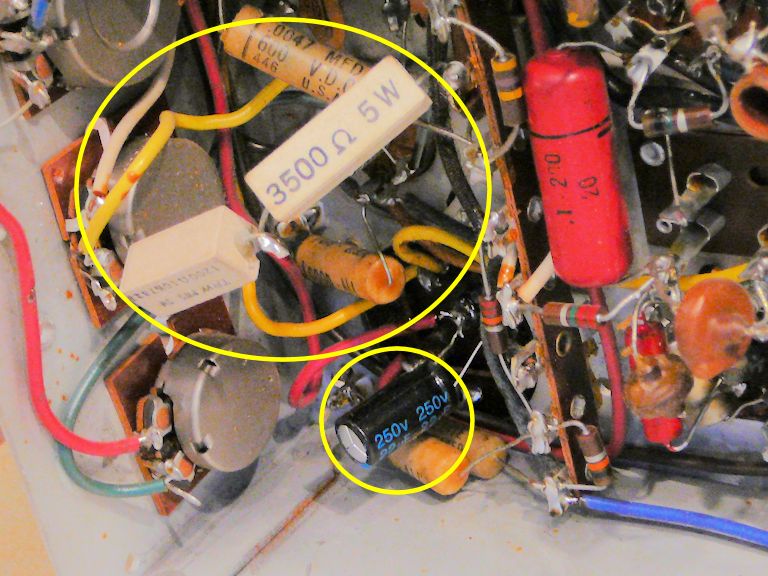 The electrolytic is piggybacked in parallel with a can electrolytic rather than taking the old cap out of circuit.  I found another new electrolytic wired between two pins of the 6AH6 video amp. The red Big Chief cap looks like an older replacement. The original paper caps are a brand that I hadn't seen before: "Good-All Marbelite." I found another new electrolytic wired between two pins of the 6AH6 video amp. The red Big Chief cap looks like an older replacement. The original paper caps are a brand that I hadn't seen before: "Good-All Marbelite."I made a couple of cursory checks and the B+ voltage seems reasonable. HV measures only 8.5KV, where that CRT normally wants something like 14KV. The TV is still full of ancient electrolytics and paper caps, so I'm not going to burn a lot of time diagnosing specifics until it has been recapped. Lacking a good place to work, who knows when that will happen? It's interesting to peek underneath, anyhow. Yes, it's an inexpensive, series-string set, but the factory wiring is tidy and the overall build quality looks decent. It's surprisingly sensitive, all things considered. When I first powered it up, it made very clear audio receiving a signal from my in-house transmitter, without anything connected to its antenna terminals. Phil Nelson Phil's Old Radios http://antiqueradio.org/index.html
|
| Audiokarma |
 |
|
|


 Linear Mode

