
|
|
|
|
|
#1
 01-04-2012, 08:42 AM
|
||||
|
||||
|
Quote:

__________________


|
|
#2
01-08-2012, 04:07 PM
|
||||
|
||||
|
Quote:
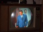
Nick, what does "high level demodulator" mean? As of Wednesday I got the cabinet up stairs and dismantled the CRT mask/safety glass/trim assembly for cleaning. On Thursday I cleaned the disintegrated rubber gasket from the Glass and mask. I used Goof Off to get the rubber off the glass, and started to use it on the mask. I then realized that it would be too harsh on the paint of the mask, and switched to rubbing alcohol, which is also not particularly good for the paint, but less harsh and yet still efficient at dissolving the rubber goo. 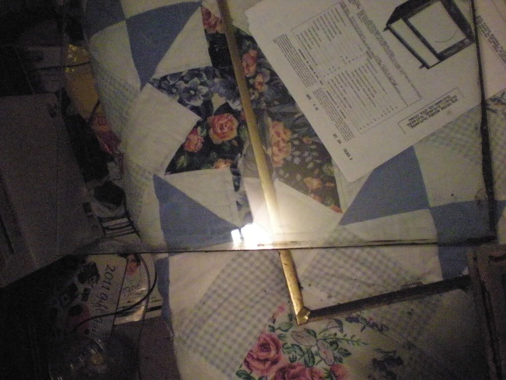 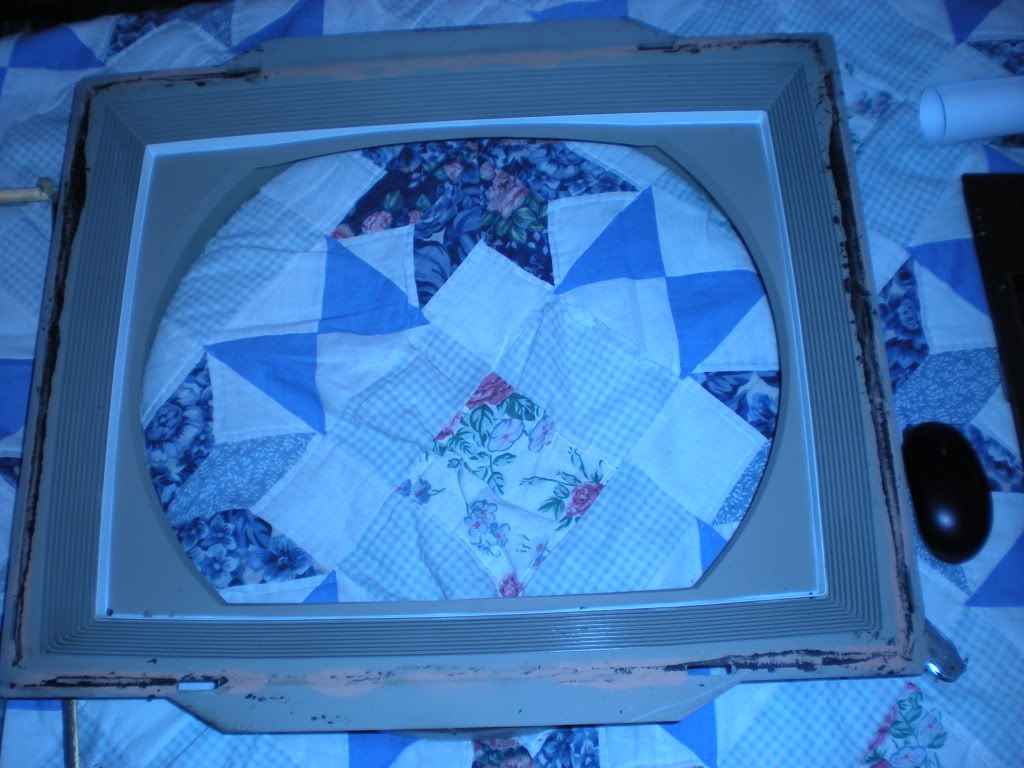 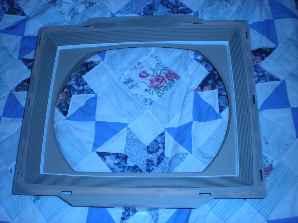 On Friday I started to polish the the the brass trim. It was not going fast at all on the lightly tarnished piece I started on. After that piece was good on Saturday, I grabbed the worst corroded piece I had and started experimenting with technique, and found that vigorously scrubbing the polish on with a tooth brush was VERY effective. Sadly even though it looks good from a distance it is clear up close that these pieces are brass plated copper, and that all pieces have spots of varying size where the plating was corroded through over the years. 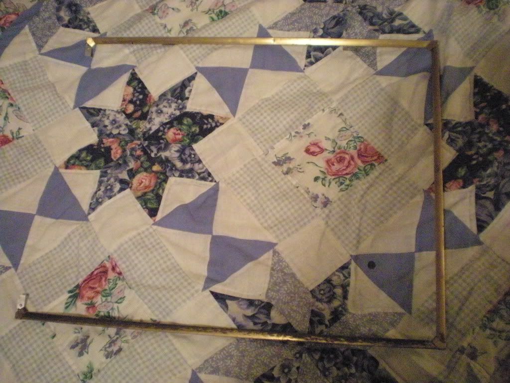 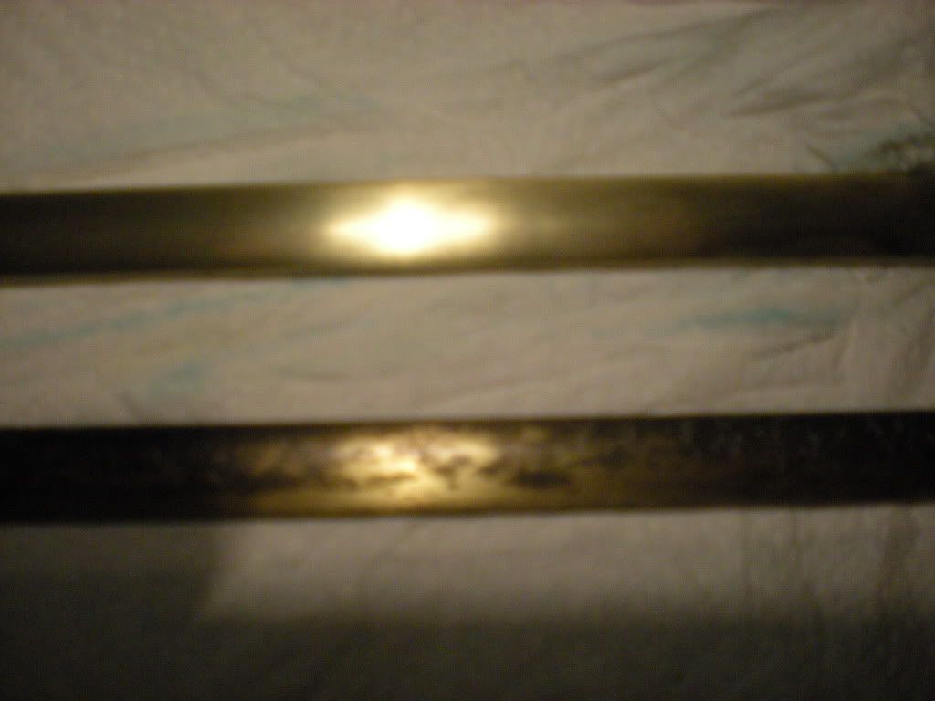 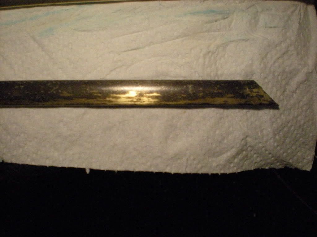 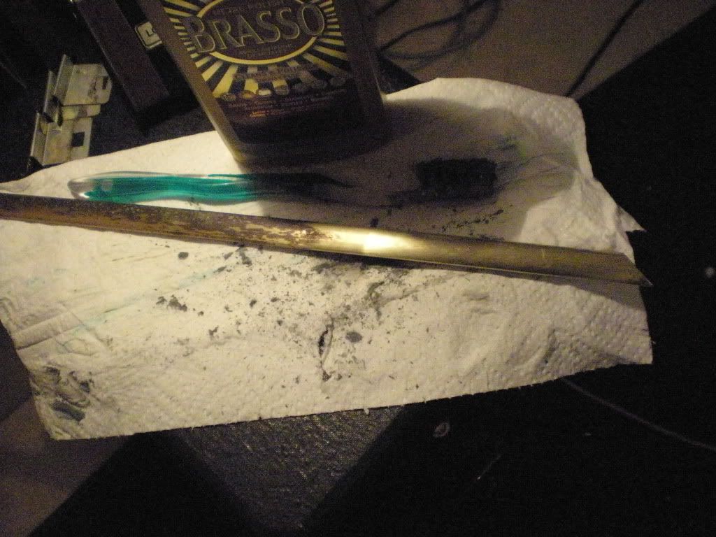 Nick I found out why those corner pieces were loose....Their retainer clips are busted. On the left is a good one the two others are the bad ones. 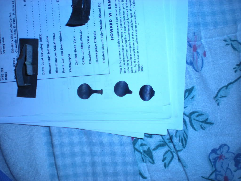 I mounted the corner pieces with the bad retainers at the top, and reinstalled everything in this picture. 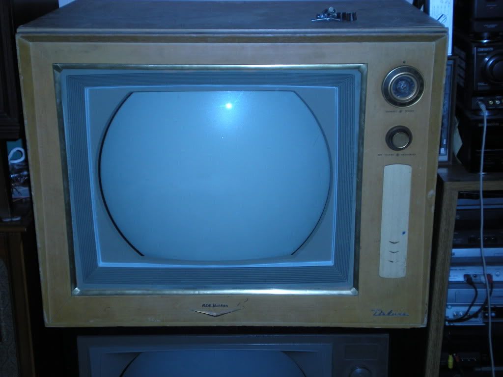 I did a quick green purity (at the time the red would not work) and neglected to take a picture. I was confounded by the red not working for some time, but then found that there was a lead touching the screen wire terminal that was shorting the screen to ground  It looked much better after that. It looked much better after that.The color circuits work, and I did some minor convergence tweaks to improve the picture. I still need to spray deoxit into some of the convergence pots as they can get squirly and mess with the deflection circuits. Still tons of adjustments to do which I'm going to need to fabricate a yoke extension cable to preform, and then hope that either the convergence will reach where I need it or that the set will not mind having the convergence yoke unplugged. 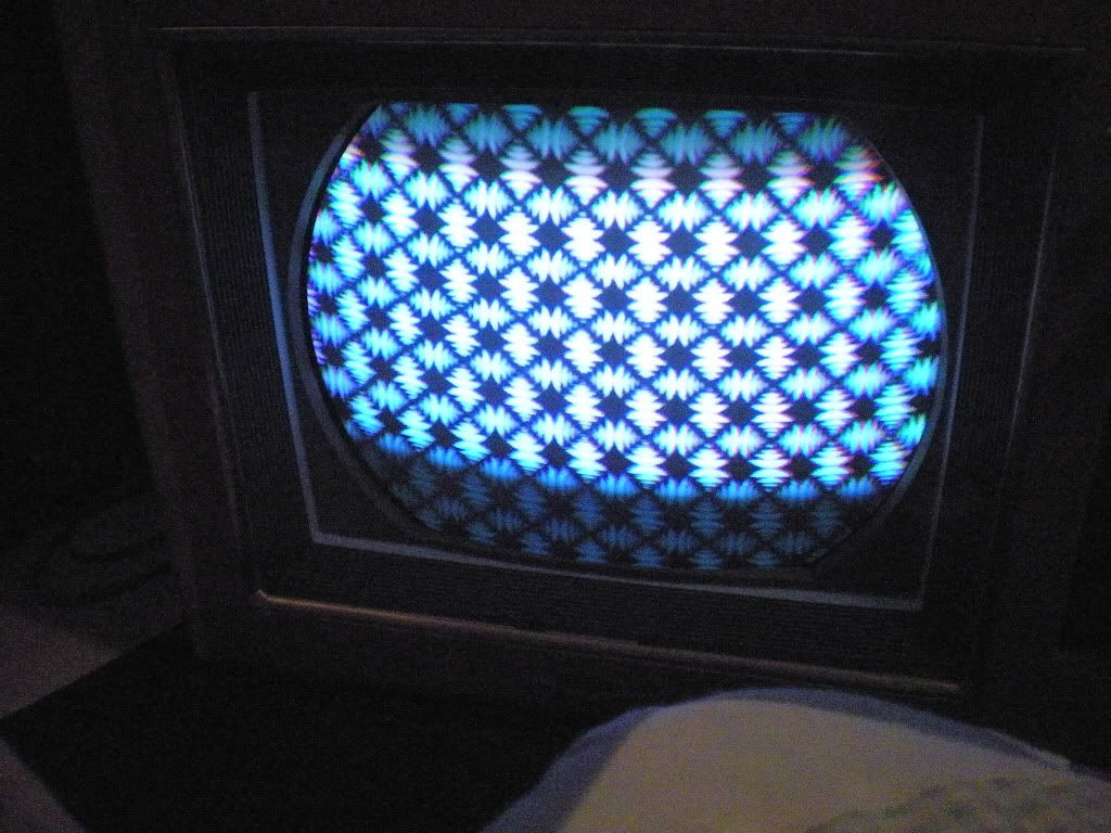 And what Nick has been wanting to see.....Color bars. 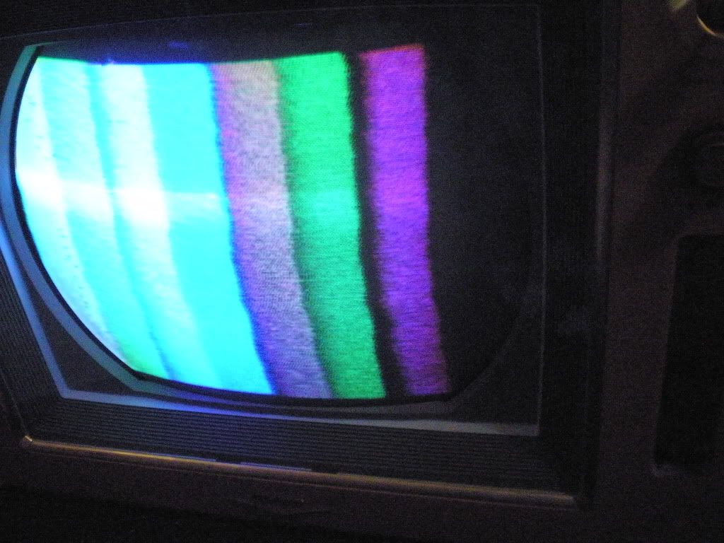 My camera made the left side look worse than it is, but it is clear that the demods need adjusting. There is a nasty imtermitant that kills the signal at the second IF tube. I'm begining to wonder if the socket is bad..... I actually lifted that set (minus the top lid) on to the black roundy my self. If it was not for the sore mussels I'd have been pretty proud of doing that.  
__________________
Tom C. Zenith: The quality stays in EVEN after the name falls off! What I want. --> http://www.videokarma.org/showpost.p...62&postcount=4
|
|
#3
12-29-2011, 12:44 PM
|
||||
|
||||
|
I used to have a busted Tektronix scope....sh!t now I wish I had not chucked it into a radio club swap meet donation auction!
So basically all tubes except the the 6AQ5s, octals, and what is inside the HV cage need to have shields. Right?
__________________
Tom C. Zenith: The quality stays in EVEN after the name falls off! What I want. --> http://www.videokarma.org/showpost.p...62&postcount=4
|
|
#5
01-01-2012, 06:27 PM
|
||||
|
||||
|
Went to Chester's yesterday and got the remaining tubes and some lytics I needed.
Yesterday night I brought it up on my variac with the plate lead of the HOT and the damper tube unpluged, and was able to tune in good sound from my signal source, and confirm that the H osc. is working properly. I didn't try for a raster as the screen voltage on the HOT was too low for me to justify connecting the HOT and damper. Also the vertical osc. appears to be dead. I haven't had enough time to do much today so far, but do know that an open 11K resistor is to blame for the low screen voltage. I may not have an exact replacement for that resistor, and will likely have to do some scrounging later on. I bought some HV lead at Chester's and striped, folded, and soldered a long section of wire at the end so that it has a decent mesh with the HV connector. Not the best, but it should be good for a test later on. I'm very happy that the RF and IF seem to be working!  With luck I may soon have a raster.
__________________
Tom C. Zenith: The quality stays in EVEN after the name falls off! What I want. --> http://www.videokarma.org/showpost.p...62&postcount=4
|
| Audiokarma |
|
#6
01-02-2012, 02:03 AM
|
||||
|
||||
|
We have got a RASTER!!
  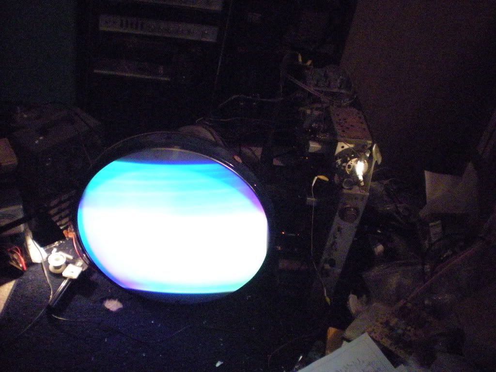 About an hour ago I finished preparations and proceeded to do a full power up including the FULL horizontal stage. The best replacement for the bad 11K ohm 10W screen resistor for the HOT I could find was a 10K 7W, but I figured that it would last long enough for a full test, and I was right. After putting the sub in with the top lead of the HOT still disconnected I read 110V. Sam's calls for 160V at the screen. I also decided not to sweat over not having the vertical osc. running the other day as I noticed that the plate of that tube gets it's voltage from the boost line, and thus would not work unless I went ahead and connected the flyback up to the HOT and damper. The HV was only 15 KV (and falling) on the second test (I was too excited on the first brief power up to read the meeter). I figure that with low HOT screen grid voltage and all new tubes across the board that this is not too bad for a first power up. I did not have sound during the test which I attribute to me messing with the tuner setting earlier in the day. This set may possibly have video for all I know. This was the last task of the night. I'll see if I can do more tomorrow.
__________________
Tom C. Zenith: The quality stays in EVEN after the name falls off! What I want. --> http://www.videokarma.org/showpost.p...62&postcount=4
|
|
#7
01-02-2012, 02:07 AM
|
||||
|
||||
|
Congrats! It;s always a good feeling when the raster appears for the first time.
__________________
"It's a mad mad mad mad world" !! http://www.youtube.com/user/mwstaton64?feature=mhee
|
|
#8
01-02-2012, 03:27 PM
|
||||
|
||||
|
We have now got VIDEO and sound!
      Well I got my signal issue sorted and did another power up. This time at the suggestion of a member of ARF to my thread there; I meetered the screen of the horizontal with the plate lead of the HOT connected, and I got 150V. This is close enough to the 160V sam's calls for that I will not loose sleep over the resistor that is in there(at least for now). When I first powered it up with signal the video was so weak I almost missed it. I did see it though and synched up the horizontal and vertical. Even with the contrast maxed the video was really weak, and the deflection would not keep synch so my mind went straight to AGC. The control was near max already and maxing it did not yield enough improvement so I started jiggling tubes in their sockets and it was the second IF tube that fixed it. In fact after shifting that tube to a better position the signal was overloading the set. A quick readjust of the AGC and all was well (except for the dead color circuits and a some other bugs). The HV stayed at about 20KV this time and adjusting the regulator would only reduce it. After about an hour of operation the fly was pretty warm. I think it is about time for me to read and preform the Sam's horizontal adjustment procedure on this set.... The screen controls were sticky and the red is stuck. Between this and the dirty tube sockets I believe that it is time to get some DeOxit and start cleaning controls and contacts. WOO HOO! Just a bit more and it will be working like new again!
__________________
Tom C. Zenith: The quality stays in EVEN after the name falls off! What I want. --> http://www.videokarma.org/showpost.p...62&postcount=4
|
|
#9
01-02-2012, 03:39 PM
|
||||
|
||||
|
Good job, Tom!!!
I knew it was a good chassis the minute I laid eyes on it, all it needed was the attention of a good tech to bring it out of hibernation. Image still looks like hell, but you can tell everything's trying to work. Worry about the color section last, for now you need to turn your attention to all the pots on the convergence panel. I promise every last one will end up having something wrong with it, and you'll never get it adjusted right without them being good. So fix all the bad pots, then move on to other sections.
__________________
Evolution... 
|
|
#11
01-03-2012, 01:58 PM
|
||||
|
||||
|
Thanks!
The main reason I could do this so fast is that I had most of the right values of paper caps on hand, and enough extra wrong values to make accurate enough (I fudged some values in the audio stages because those stages are not critical, and I rarely use the sound on my sets) replacements for values I was missing. I also was on Christmas break, and until today I was able to dedicate the better part of a few days on end to working on it. My plan of attack will be to get De Oxit tonight to clean contacts, and this week end swap the CTC4 cabinet in the garage for a roundy in my bed room/work shop/display area/big mess. Then once I have the CRT mounted in the cabinet I will concearn my self with the deflection tweaks, and then color issues. I'll have some questions soon. Gota run!
__________________
Tom C. Zenith: The quality stays in EVEN after the name falls off! What I want. --> http://www.videokarma.org/showpost.p...62&postcount=4
|
|
#12
01-03-2012, 05:40 PM
|
||||
|
||||
|
You've made excellent progress with this one, must have given you goosebumps when finally a picture appeared on the screen
 Great stuff, you'll have nice set when its all done! Cheers. Great stuff, you'll have nice set when its all done! Cheers.
__________________
Visit my Vintage TV & Radio Page - http://nzvintagetvradio.blogspot.com/ My YouTube Link - http://www.youtube.com/user/glenz1975?feature=mhsn Last edited by Glenz75; 01-03-2012 at 05:56 PM.
|
|
#13
01-03-2012, 07:35 PM
|
||||
|
||||
|
Thanks!
I was barely able to get any video at first and almost did not notice that I even had any. Once I got it to synch I was briefly very excited, but it was so weak that it was difficult to tell what I was at on low contrast images. This and the unstable synch (the signal was so weak that I could barely even get a picture of the synch bar when the vertical rolled) quickly made my inner technician take over and start trying to improve the signal using any tricks at my disposal. Once I succeeded at getting the video back to a reasonable level I went right back to excitedly celebrating this significant mile stone, and proceeded to watch, for an hour, a level of picture quality that I would not bother to watch on any other set I own. I will admit that I enjoyed watching it more than any of my other, presently much better preforming, restorations. Now that I have time to type more I have three questions for those whom have used these sets with the newer roundy tubes. First is it a good idea to keep using the field neutralizing magnets on the front of the CRT with a 21FJP? Second those knurled metal things on the outside ends of the convergence yoke that point towards the back of the set, are they the static convergence adjusters? Third is how do I preform safety glass removal on a CTC4? This set is nearly a decade older than any color set that I've worked on before so it is a real learning experience of how they designed them in the early days, and a good chance to sharpen my trouble shooting skills and put those skills to the test.
__________________
Tom C. Zenith: The quality stays in EVEN after the name falls off! What I want. --> http://www.videokarma.org/showpost.p...62&postcount=4 Last edited by Electronic M; 01-04-2012 at 12:55 AM. Reason: add a question.
|
|
#14
01-04-2012, 12:59 AM
|
||||
|
||||
|
Quote:
I tried to use them with a glass tube, but they are too weak to fix impurities in the center of the screen. I also gave you that plastic ring with the hairpin magnets on it right? CTC-9 chassis use the same thing, I'd strap that to the back of the tube and see if you can get good purity between that and the edge purity magnets from the CTC-4. The hairpins come in pairs and I think one is missing. You'll want to remove that one... Quote:
More like beam positioning, but call it what you will. Basically you center all the dynamic convergence controls, then use the knurled knobs on the conv yoke to set up a roughly converged center cross pattern. From there, you follow the Sams dynamic proceedure RELIGIOUSLY till it starts to look better. Then you do it 5 more times till it looks right. Oh, don't forget to do red purity before any of that other stuff. Purity first, then convergence. ETF has the CTC-4 Sams posted if you don't already have one. Quote:
__________________
Evolution...
|
|
#15
01-05-2012, 08:38 AM
|
|||
|
|||
|
Actually, the 4 was one of the easier sets I've worked on. Most things remained about the same after the CTC-4 and 5, which were each special in their own ways. The 4 detected color on different axes than any other set before or after: R-Y and G-Y vice the typical R-Y and B-Y that came later, or I/Q that came before, along with having high level demod. The 5 had a funky demodulator circuit using 12AT7's. The CTC-7 and everything thereafter looks the same on paper, subtle changes only. Most of it is different tube types, but later ones also shed an IF stage or 2 due to getting tubes with higher gain.[/QUOTE]
Nick.... The CTC5 had two different chassis that year. The better model had a color circuit that was simular to the later chassis.
|
| Audiokarma |
 |
|
|




 Hybrid Mode
