
|
|
|
#31
 03-13-2014, 04:35 PM
|
||||
|
||||
|
Looks like a Hoffmuntz.


|
|
#32
03-13-2014, 05:41 PM
|
||||
|
||||
|
This is a little different. These two items protrude through the rear panel as adjusters. The lower one looks like it would lever the core (?) up and down. The upper one terminates in something like a switch at the base of the coil. If these are HV adjusters, it's a new type to me.
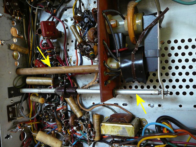 Today's puzzle: I see this little empty socket near the 3rd IF section. Wonder what goes here?  There are no empty sockets elsewhere on the chassis, so presumably it's for some plug-in component, not a cable. Underneath, one terminal of the socket goes to ground and the other two are wired to a little network of resistors and (peaking?) coils that go to the 3rd IF stage and (through the big pink .1 cap) to the video amp.  The TV has loud and clear audio and the sound takeoff appears to be from pin 5 of the video amp, so presumably a signal is getting to that tube with nothing plugged into the mystery socket. I don't know why you'd have a plug-in component here unless it's something optional or variable. Could this be some kind of local/distance thingie plugged in by the dealer in certain locales? Phil Nelson Last edited by Phil Nelson; 03-18-2014 at 01:52 AM.
|
|
#33
03-13-2014, 06:09 PM
|
||||
|
||||
|
Quote:
Quote:
Did the green glow return after sitting overnight? jr
|
|
#34
03-13-2014, 07:08 PM
|
|||
|
|||
|
Quote:
The shaft the adjusts the flyback core gap is the width control. I would turn it fully clockwise, for now. The other shaft is for the horizontal centering. Regarding the tuner: It could a Standard Coil. If the strips are in one piece, someone else made it! BTW, the set is a parallel wired set. IDK, if the transformer has a winding for the damper tube or a secondary tap. 
|
|
#36
03-13-2014, 11:01 PM
|
||||
|
||||
|
Looks like a test point to me. I will quit fretting over it. The schematic shows their 3-position range switch in the same neighborhood, so perhaps my local/distance guess wasn't completely insane.
Unfortunately, the green glow seems to be gone for good, no matter where you put the ion trap. It was fun to see, anyhow, even it seems a little gimmicky. I can see using it for a coarse setting, but I'd want to make the final adjustment looking at the screen. The CRT is indeed a Rauland and its label has some instructions about using the green marker. Sooner or later, I'll loosen the retaining strap so that I can read the whole thing. 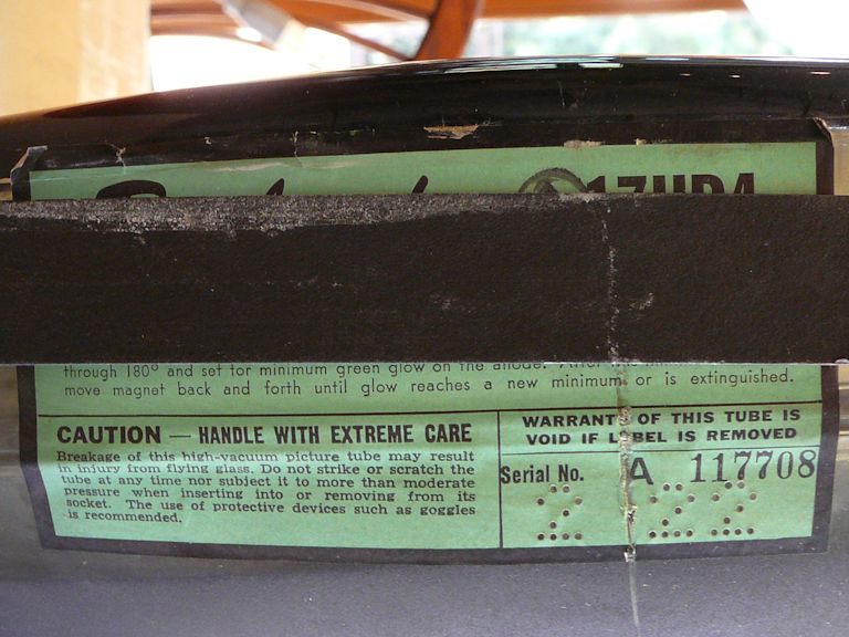 The tuner appears to have two strips per channel; it looks like the one in my Admiral console. Thanks for the other advice. I'll check out that replacement resistor (and the replacement caps, for that matter). Regards, Phil Nelson
|
|
#37
03-14-2014, 12:38 AM
|
||||
|
||||
|
OK, I'm going to quit dissing this poor little $20 craigslist Hoffman.
 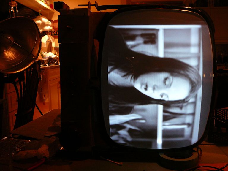 After replacing paper caps in the horizontal and sync sections, I decided to sub the 1B3GT and 6BQ6 tubes, out of superstition. (The others tested good, but you know.) I had also scrubbed the 1B3GT area with alcohol and given that resistor a good hard look. When I went to play with the ion trap one last time -- bingo! -- the green glow was back, and within seconds I had a bright picture with terrific contrast and sharp focus. Don't ask me why someone put a brightener on this CRT. It looks as strong as a new one. The second photo is receiving a cable broadcast with rabbit ears from my in-house transmitter, a decent real-world test of any old TV. A little blurry, but that's how all of my photos of live broadcasts seem to turn out. Tomorrow I'll do some grown-up stuff like clean all of the pots and adjust the screen geometry, etc. It's fun to see it wake up, anyhow. Phil Nelson
|
|
#38
03-14-2014, 09:54 AM
|
|||
|
|||
|
Quote:
I worked on a Hoffman set, that was a year or two newer. It was real impressive, for a 21" table model. A 6X9 speaker on one side, an 8" speaker on the other and push-pull audio output. It had that crazy Standard-Coil UHF-VHF tuner, with the two coil turrets, four stages of IF and large power transformer with two 5U4's. Hoffman was really a high-end line at the time. This model had the easy-vision tinted safety glass.
|
|
#39
03-15-2014, 06:44 PM
|
||||
|
||||
|
Nice picture for such a basic, low-end-appearing TV set.
This is the first non-tinted Hoffman I have seen, not counting the one color set I have been in contact with.
__________________
Chris Quote from another forum: "(Antique TV collecting) always seemed to me to be a fringe hobby that only weirdos did."
|
|
#40
03-18-2014, 01:25 AM
|
||||
|
||||
|
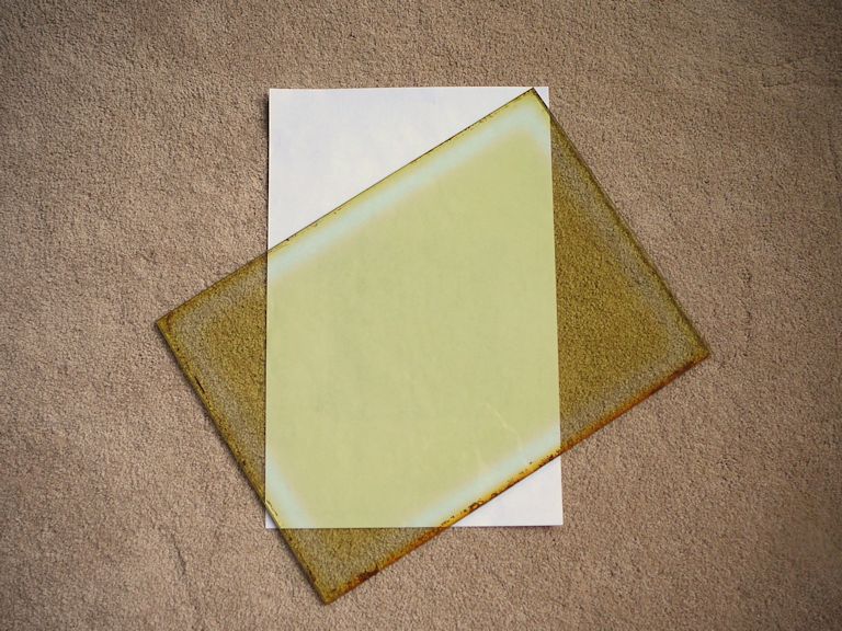
The safety glass is tinted. I thought it was just grubby until I removed the glass for cleaning, but if you photograph it against white, the color jumps out. It's sort of a greenish amber.
 After recapping, the TV is working nicely except for a slight horizontal non-linearity and lack of width (see previous test pattern). The air-gap "width" adjuster mentioned earlier adjusts the HV output directly; I can get anything from 8KV to 10KV by turning it in or out, which makes the entire screen image grow or shrink. At 10KV, it's much too small and at 8KV (as low as I can go), it doesn't quite fill the mask horizontally. I have the feeling that it would fill the screen if I could just correct the linearity, but the TV has no horizontal linearity adjuster. Here's the schematic for anyone who's curious. http://antiqueradio.org/art/Hoffman7M112Schematic1.jpg http://antiqueradio.org/art/Hoffman7M112Schematic2.jpg http://antiqueradio.org/art/Hoffman7M112Schematic3.jpg Perhaps there's a solution, but I'm not sure how much I can expect from this set. I wouldn't mind the minor non-linearity if it would just fill the dinged-danged mask. Phil Nelson Phil's Old Radios http://antiqueradio.org/index.html Last edited by Phil Nelson; 03-18-2014 at 01:28 AM.
|
| Audiokarma |
|
#41
03-18-2014, 08:24 AM
|
|||
|
|||
|
Quote:
Interesting!
|
|
#42
03-18-2014, 09:10 AM
|
|||
|
|||
|
Quote:
|
|
#43
03-18-2014, 10:39 AM
|
||||
|
||||
|
They didn't use Plexiglass.
I have a 49 Hoffman glass right in front of me and it consists of a sheet of 3/32" clear bonded to a sheet of 9/32" green glass. I have seen other 49 Hoffman sets that just had thick green glass but I have never seen one made of plastic. I have read that the green glass was surplus glass from a building project in Los Angeles but I have my doubts. If the glass Phil has is bonded I suspect the plastic material may have just discolored with age.
|
|
#44
03-18-2014, 11:12 AM
|
||||
|
||||
|
Yes, it's bonded like other safety glasses I have seen. If it was originally clear, maybe I'll replace it. This color isn't very appealing.
Any ideas about the linearity issue? Phil Nelson
|
|
#45
03-18-2014, 11:26 AM
|
|||
|
|||
|
Horizontal linearity could be...
Problems with these .1 across L21 120mmf across Damper tube 12ax4gt 47mmf across 1/2 of Horiz Yoke winding the 12ax4gt itself... I would guess you already tested such... Try about a 75mmf across the damper tube to see if there is an improvement. Have a nice afternoon... rrrhre2s
|
| Audiokarma |
 |
|
|


 I found another new electrolytic wired between two pins of the 6AH6 video amp. The red Big Chief cap looks like an older replacement. The original paper caps are a brand that I hadn't seen before: "Good-All Marbelite."
 Linear Mode

