
|
|
|
#76
 11-02-2014, 10:53 AM
|
||||
|
||||
|
Have you disconnected or replaced caps C503/C504 from the AC line to the chassis ? Have you checked R501 - 270K from one side of AC to chassis ?
It's been my experience that width coils have only a minor effect on the width are are used for fine adjustments. So your width issues might well be another component or tube in the horizontal circuit. 
|
|
#77
11-02-2014, 07:46 PM
|
||||
|
||||
|
The the pictured test above C503 and C504 (and pretty much everything in the set) was disconnected. R501 is within tolerance.
I went through all the major tubes in the horizontal circuit and tested with alternates with no effects to the control. Just about every resistor in the circuit have also been confirmed for being within tolerance. All that is left are the ceramic and mica capacitors which I do not have any easy way to test. The first thing I was looking into replacing were the ceramic dogbones as there are at least three in the horizontal circuit with one of them directly in the width control circuit (C417). I just need the time to go to Vancouver again and order them. Edited: The socket was dismantled and rebuilt using new plastic insulators instead of bakelite. The results were odd. Neutral side was now 0v between chassis and ground (to be expected) but the positive side to chassis was 90v with nothing yet soldered to the socket. Short of ceramic I can't think of anything better tha plastic that can insulate so I'm completely stumped. I reassembled everything and with the disc caps reinstalled both sides are now 60v again. Forget it. I'm going to have to walk away from this one.  You know what? I think I'm going to play it safe and stop here for now. No more guessing and replacing hardware until we really know what is wrong. For some odd reason my vertical linearity is skewing itself now and these little issues are starting to creep up.  I'll show the schematics to a few more people and see if they can offer any ideas but otherwise I'm completely out of things left to check on any of my current problems. I might even say the hell with it and call it finished. Last edited by MIPS; 11-02-2014 at 10:00 PM.
|
|
#79
11-03-2014, 10:18 AM
|
|||
|
|||
|
Just a heads up- In your photo above showing the two disc caps, a leg of one cap (the upper one) is dangerously close to touching the housing and giving you a hot chassis.
|
|
#81
11-04-2014, 07:44 AM
|
|||
|
|||
|
good catch old coot 88(i didnt see that) and good advice n21xk!
i'm gonna try a 21st century vid phone(skype) service call with mips to get this set sorted out. got a lot going on but will do my best. did a few basic "virual service calls" over the years with non tech friends with great success so im hopeful. it will be easier with a tech (mips) on the other side of the cam! heck-its possible to have several videokarma members advising live using tinychat-is this a new better way to assist vintage tv collectors? new trend? ha!
|
|
#82
11-04-2014, 11:07 AM
|
||||
|
||||
|
Yeah I'll fire you a message over Skype and I'll see if I can setup for a call in the next day or so. I wonder if I can get the webcam to behave..
 In the meantime I fixed that precariously close wire and did a test fit of everything back in the cabinet. It seems I've neglected to notice I've lost a knob. Uses the keying similar to that used for the mode selector but in this case it's for the contrast. We'll talk about looking for that as well. Tuning needle is also out of alignment by an inch, otherwise there wasn't any other problems. 
|
|
#83
11-05-2014, 08:49 AM
|
|||
|
|||
|
Hey Members,
thought i would update on the virtual(skype videophone) service call. 1st of all-Great work Mips! i found giving tech advice is So much easier/better skypeing than typing-lol! the future perhaps? problem #1- two waveforms not correct- scope was set to roughly vert freq-when switched to horz freq-waveforms were correct.Mips found this out before the call. problem#2-too much width-from what i could see, width was close enough-after all, vintage sets are not that accurate-most look fine with designed tolerances at 20%. And i have found over the years that a lot of sets that vintage had very little affect adjusting the width. problem #3-ac leak to chassis.-leaky ac jack-never seen this one but Mips found the problem before the call. problem #4-radio dial out a bit- readjust pointer on dial cord to match station frequency being recieved.ussally an easy fix versus an alignment. problem#4-vertical rolls when adjusting vert height for best picture-height looked good enough to me during the call and vert hold was in the middle of the pot but in hindsite-i should have mentioned that you sometimes have to readjust vert hold while changing vert height/lin-maybe Mips already knew this. problem #5-knob missing-suggested that Mips post a picture of it on here and arfs classified section. problem#6-picture is slightly darker near top of crt-thought it might be a neck shadow but didnt quite look that way to me. Mips mentioned that the tv had uneven sunlight casted on it for a long time so perhaps phosphors could have been affected? in hindsite,i thought that if this is so,you should be able to see a slight difference in the color of the crt phosphor with the set off? it reminded me of a set i fixed years ago where the set was played for a long time with too little height. by the time i got it, the phosphor was brighter where the scan had missed -looked at 1st glance that there was slight vert"foldover". you could see the different color of the phosphor with the set off! problem#7-while vert height was being adjusted, a pf range disc cap blew in the horz section-i thought it was just a coincidence-never heard of a cap blowing in horz while adjusting vert section. most likely a original disc cap ready to blow(across the horz yoke iirc) Problem#7-at one extreme adjusting vert hieght, the scan almost collapses down to aprox 1 inch. but i could see that the vert osc and amp were still working-not a complette collapse-my thoughts are that perhaps with this early desigh, that this is normal. the set can be adjusted for acceptable picture. Mips has replaced most caps(except some ceramics/discs)/checked most resistors. Question#8 Mips showed me some tubluar ceramic caps and wondered if he should change them-iirc, they are ussally good---Mips-could you repost a picture of those caps? any thoughts from the forum? RonL
|
|
#84
11-05-2014, 09:08 AM
|
||||
|
||||
|
#6 for anything like this, just turn the yoke and see if the problem moves, or not,
with the new yoke position.... Does it look ok with regular broadcast signal....? .
__________________
Yes you can call me "Squirrel boy"
|
|
#85
11-05-2014, 10:54 AM
|
||||
|
||||
|
Now that I'm spending more time looking over photos of other working sets I guess it seems alright to be missing a few inches from the edges, especially on roundies. Regular broadcasts are fine otherwise but you better hope that shows with subtitles use small text or else you'll be missing the ends. Just look at the photo above for a better idea on how much if the image gets cut off. I can fiddle with the yoke again to see if it is just neck shadow I'm experiencing but under most conditions it's hard to notice. I really like the whole assembly this set uses to support the yoke compared to later computer CRT's I've had to tweak. Everything is either secured with wing nuts or simple screws and it will all stay in place when you are not touching it.
As for those dogbone ceramic caps, there's one in the center of the photo. You can see another one hiding under an orange drop.  Really it's not too hard for me to replace them because new ones cost only a few cents, if not just under a dollar. They just seemed really out of place compared to every other ceramic capacitor in the set and there's three of them in the same general circuit. The width thing was making me pull all sorts of assumptions. Got knows how much time I wasted but hey, at least it was less variables to deal with. Quote:
 I'm going to replace that one blown disc cap, the filter caps and a couple 220k resistors because what the heck, it's only $1.50 in parts and I believe we're done with the electronics finally. Again, thanks for the help ronl. Last edited by MIPS; 11-05-2014 at 11:02 AM.
|
| Audiokarma |
|
#86
11-05-2014, 12:42 PM
|
||||
|
||||
|
Dogbone ceramics are very reliable and have good temperature characteristics. They are only used in sensitive circuits and I wouldn't mess with them. However if you do attempt to replace any, make sure to use mica or CG0/NP0 type ceramics.
|
|
#87
11-05-2014, 01:25 PM
|
||||
|
||||
|
Regarding issue #6, I had one CRT whose edges were noticeably brighter than the center area where scanning had occurred. In this photo I used tape to mark the boundaries.
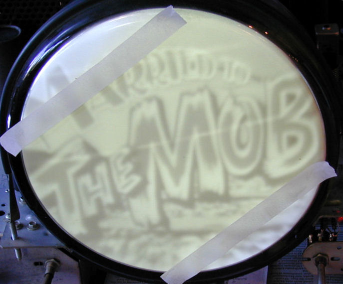 My solution was to rotate the CRT so that these areas were hidden by the mask (as they had been originally). I assumed that this was caused by long use. You can read more about this at http://antiqueradio.org/RCAT-100Television.htm . To test whether the phosphors in your CRT have faded, you can simply rotate your CRT a bit and see whether the shadow rotates, too. As you have figured out, it's normal with every round CRT for the extreme corners to be cut off. By definition, the TV image is a rectangle, not a circle. The mask on your TV also has rounded corners, so if you adjust height and width to just fit the mask, the extreme corners will still be hidden. That said, in your last photo the height and width seem excessive. I would normally expect to see all of that big circle. If you reduce the height and width -- as long as you don't create black bars around the edges -- you'll see more of the image. On some TVs, trying to achieve perfect geometry is a losing battle. I think some TVs were deliberately designed with a little overscan so that customers wouldn't constantly call the repairman when components aged and black bars appeared on the edges. And some sets give you more adjustment leeway than others. If you work with your adjustments long enough, you'll eventually find the best compromise for your particular TV. Then it is time to put away the test patterns and enjoy watching normal programs  Phil Nelson Phil's Old Radios http://antiqueradio.org/index.html Last edited by Phil Nelson; 11-05-2014 at 01:39 PM.
|
|
#88
11-05-2014, 03:57 PM
|
||||
|
||||
|
Reminds me of the Cheech and Chong audio skit, where one of them pays a visit to see the other, the visitor asks what he's watching on TV. "It's a movie about Indians, but it's really boring". "That's not a movie, that's a test pattern".

__________________

|
|
#89
11-05-2014, 04:57 PM
|
||||
|
||||
|
Quote:
I agree that your set seems to overscan a bit more than this. Here is an image I lifted from the internet illustrating the 2 parameters that I mentioned.
__________________
Tim
|
|
#90
11-05-2014, 09:27 PM
|
||||
|
||||
|
The height can be adjusted with a lot of fiddling with linearity and vertical hold but the width has been the problem that's frustrated me for the last two weeks simply because the only control does pretty much nothing at all. Either the circuit was always a really weak one or I simply can't find the fault.

|
| Audiokarma |
 |
|
|


 Linear Mode

