
|
|
|
#121
 03-12-2015, 03:01 PM
|
||||
|
||||
|
I have begun to investigate the red-plating condition on the 6CB5 horizontal output tube. I pulled the HOT, VOT, and damper tubes in hopes that I can safely check voltages & waveforms. The yoke and convergence coils are connected.
The screen grid voltage (pin 1-8) on the HOT is MUCH too high, about double the expected voltage. The resistors between that point and the +350V supply (R140, R141) check out OK. (These are Sams numbers.) The cathode voltage (pin 3) is in the ballpark, measuring -25V where -23V is expected. Moving back to the 6SN7 horizontal oscillator tube, its resistances look reasonable but its voltages are off. Instead of -85V at the grid (pin 4), I measure -1.5V. The expected waveform (W13) at point L is not correct. It is a muddy slope similar to W14 instead of the classic W13 waveform with the rounded shoulders and nice peaks that I saw the first time I powered up the TV: 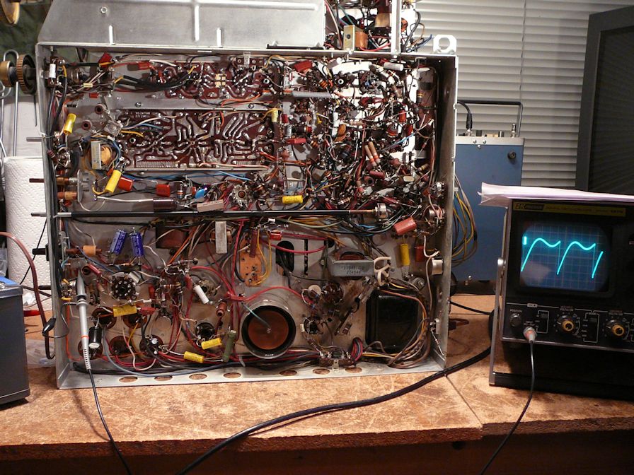 The horizontal has always been rock-solid on this set, so it's disappointing to see it degrade. Subbing oscillator tubes had no effect on voltages or that waveform. I hope I'm not barking up the wrong tree in checking these things. I hope even more that the flyback hasn't failed. Besides checking components around the oscillator, I'll see what I can learn by testing resistances on the flyback. Phil Nelson 
|
|
#122
03-12-2015, 06:36 PM
|
||||
|
||||
|
Here's the schematic showing the horizontal tubes mentioned in my last post.
Phil Nelson 
|
|
#123
03-12-2015, 09:46 PM
|
|||
|
|||
|
Quote:
|
|
#124
03-12-2015, 10:37 PM
|
||||
|
||||
|
Yes, I have a B&K Analyst 1077B that can produce a horizontal grid drive signal.
I assume you mean injecting that signal with the HOT and damper tubes back in place. I will keep a close eye on things and shut down immediately at any sign of trouble. Phil Nelson
|
|
#125
03-13-2015, 01:33 AM
|
||||
|
||||
|
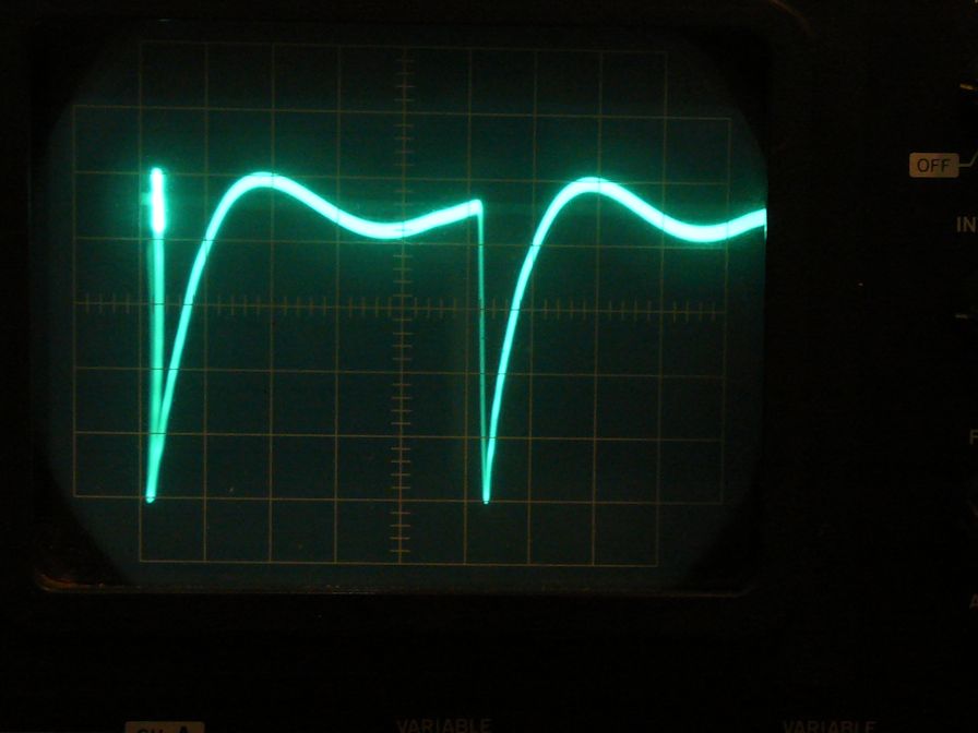
Here is the TV Analyst's horizontal grid drive signal. Very stable.
 I disconnected C115 at its junction with R138/R139 and injected the signal there. With tubes back in place, the screen grid voltage at pin 1-8 dropped from 350V+ to around 125V (160V expected) and the HOT did not red-plate. The voltage at grid pin 4-5 was -75V instead of the expected -38V. Out of curiosity, I reconnected C115 and tried the set without the injected drive signal. The HOT red-plated and I shut down immediately. Which suggests something fishy upstream of the HOT, I guess. This was done on the workbench. I suppose I could set the chassis behind the cabinet and connect to the CRT with this setup, if it's important to look at the screen and judge whether the flyback is still alive. I don't have extension cables for the yoke/convergence/CRT, but the original cables reach if I put the chassis on a big box. It's just hard on the back to crouch down on the floor to measure things  Phil Nelson
|
| Audiokarma |
|
#126
03-13-2015, 10:14 AM
|
|||
|
|||
|
I think you can safely presume the fly is OK and the problem lies entirely in the osc. area. I would concentrate on getting the osc running right as the first order of bizness.
|
|
#127
03-13-2015, 12:42 PM
|
||||
|
||||
|
I will check things around the oscillator tube. The tubular caps and resistors were eliminated long ago. That leaves a handful of mica caps + the various coils.
Phil Nelson
|
|
#128
03-13-2015, 02:34 PM
|
||||
|
||||
|
Resistors fail randomly sometimes, and a tiny percentage of new caps are bad shortly after failure....Don't discount all possibilities.
__________________
Tom C. Zenith: The quality stays in EVEN after the name falls off! What I want. --> http://www.videokarma.org/showpost.p...62&postcount=4
|
|
#129
03-13-2015, 05:50 PM
|
||||
|
||||
|
I like that you gave the pet shelter extra $ - man, that's such a clean looking tv. My wife is crazy about these older tvs, too. I'll have to show her this one. Like the rest here, I'm hoping for the best, even if you don't need yet another project.
Phil R.
|
|
#130
03-13-2015, 06:48 PM
|
||||
|
||||
|
Yay, the oscillator is oscillating again.
 I replaced three mica caps and a couple more resistors in the horizontal AFC/osc circuit and my favorite waveform is back. Also HV (25KV) and a screen image. Two of those micas (C106, C110) were rated for 1KV, so I tend to point the finger at them, although I have no way to test a 1KV cap. Which puts me back where I was a week ago, wanting to see some color in those dratted color bars. Before messing with color, though I'm going to behave responsibly for a change, and work through the procedures for HV adjustment and HV performance check. The manual says that involves measuring current at the 6BK4 regulator cathode as well as at the HV fuse. Interestingly, when I put on a color bar pattern, I saw some rippling waves of color, rather than monochrome bars, and the Color and Hue controls actually had some effect on the image -- the first time ever. That gives me hope of solving the color issue eventually. But first I need to do the HV adjustments and some other voltage checks, so I can play the set for more than 60 seconds without fearing a meltdown. Thx again for the advice. Phil Nelson Phil's Old Radios http://antiqueradio.org/index.html Last edited by Phil Nelson; 03-13-2015 at 10:07 PM.
|
| Audiokarma |
|
#131
03-31-2015, 02:04 PM
|
||||
|
||||
|
After a detour to restore yet another CTC-11 (which needed very little work), I'm preparing to tackle the color issue again. In the meantime I got a new pattern generator with variable chroma output, which should be ideal for following up on Nick's suggestion to vary the chroma while looking at a tube such as the chroma bandpass amp.
While I have the CTC-11 on the workbench, it seemed a good time to try this method and see what the results look like on a similar TV that displays color very well. Here's an animated GIF showing pin 1 of the CTC-11's chroma bandpass amp (6AU6A) at 0%, 50%, and 100% of chroma output from the generator:  Pin 1 of the chroma phase detector (6AL5) also has a waveform that changes obviously in response to varying chroma input:  My idea is to get the CTC-4 back on the bench and scope the bandpass amp and phase detector and watch for change when I vary the generator's chroma output. I hope this will answer the question whether a usable color signal is making its way through the TV's video IF section. We're leaving tonight for a mini-vacation, so I may not be able to try this until this weekend. Phil Nelson
|
|
#133
04-03-2015, 08:33 PM
|
||||
|
||||
|
Yes, I await the results of your always-informative tests and comments, Phil. Good luck with the set.
__________________
Chris Quote from another forum: "(Antique TV collecting) always seemed to me to be a fringe hobby that only weirdos did."
|
|
#134
04-04-2015, 01:47 PM
|
||||
|
||||
|
Back to the CTC-4. Here are comparisons of the signal at the video amp input. The first photo shows the CTC-11, which makes a nice picture with accurate colors. On the bottom is the video output direct from the generator. Above it is the output from the CTC-11's IF section, where it enters the video amp.
 The CTC-11 IF output isn't perfect, but it resembles the color-bar signal and it seems to have a healthy burst signal. My reason for looking at this is to understand what the video amp input should look like in a similar color TV that works normally. Next is the CTC-4's IF output where it enters the video amp. Here, the direct color-bar signal from the generator is on the top and the CTC-4's signal is on the bottom. 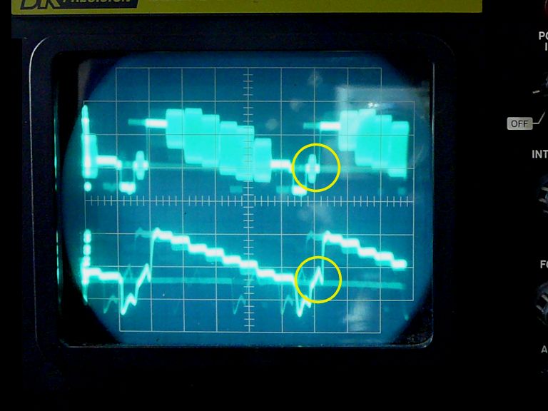 The CTC-4 signal is attenuated, to say the least. I have a bad socket on the IF board, the 3rd video IF amp. I have cleaned the devil out of that socket, swapped tubes, etc., but the socket is very intermittent. Only by nudging the tube into exactly the right position will it pass a signal at all. In the wrong position the screen goes completely dark. I did scope some of the CTC-4's color tubes (chroma bandpass amp and chroma phase detector), but the photos aren't worth including. Those waveforms look like no usable color signal is present. There's obviously something wrong with the IF socket, so I guess I'll address that, either by ordering a replacement socket or trying to transplant new pins into this one (a trick I haven't tried before). Phil Nelson
|
|
#135
04-06-2015, 12:18 AM
|
||||
|
||||
|
Phil, your step-by-step analysis and documenting of the process are enjoyable and informative, as always. I wish I had something to add, but I can only think that it might be an IF alignment issue.
Another trick would be, inject a color baseband video signal into the stage where you are seeing the total lack of color signals/frequencies (the lower trace in your CTC-4 scope picture) and see if the rest of the set's color circuitry works OK. Then, inject the same signal but at IF, into the IF stages one by one backwards and see if you can narrow down where the problem starts. Suitable signals should be available from your B&K 1077, I think.
__________________
Chris Quote from another forum: "(Antique TV collecting) always seemed to me to be a fringe hobby that only weirdos did."
|
| Audiokarma |
 |
|
|


 Linear Mode

