
|
|
|
#16
 07-14-2018, 10:04 AM
|
|||
|
|||
 Quote:
That set's a little trickier to troubleshoot because it uses a floating B- line instead of a hot chassis.

|
|
#17
07-14-2018, 10:42 AM
|
|||
|
|||
|
Quote:
I just spent a half hour trying to find the B+ source. It seems it's sourced from the cathode of the 12SN7, 2nd clipper. Slightly harder schematic to understand! Even the Sams isn't much better.
|
|
#18
07-14-2018, 11:24 AM
|
||||
|
||||
|
Quote:
__________________
Tom C. Zenith: The quality stays in EVEN after the name falls off! What I want. --> http://www.videokarma.org/showpost.p...62&postcount=4
|
|
#19
07-14-2018, 12:10 PM
|
||||
|
||||
|
Quote:

|
|
#20
07-14-2018, 12:35 PM
|
||||
|
||||
|
Quote:
__________________
"If it isn't broke, you aren't trying hard enough"
|
| Audiokarma |
|
#21
07-14-2018, 09:00 PM
|
|||
|
|||
|
Quote:
|
|
#22
07-15-2018, 09:58 PM
|
||||
|
||||
|
So, does anyone have any good tips to keep troubleshooting? I've gone through the schematics up through the power supply, but haven't really checked much else.
__________________
"If it isn't broke, you aren't trying hard enough"
|
|
#24
07-16-2018, 08:41 AM
|
||||
|
||||
|
Tubes light for about 30 sec and then they sorta flicker on and off and there's still something causing my caps to fry as well. The filament circuit problem is just caused by the faulty electrolytic caps, but I can't figure out what causes my electrolytics to fail in the first place. Some of the caps that were around 10-20uF are now testing in the hundreds range.
__________________
"If it isn't broke, you aren't trying hard enough"
|
|
#25
07-16-2018, 09:28 AM
|
||||
|
||||
|
The filament circuit should not be affected for the caps. There are two series filament strings that connect directly to the AC line through a ballast resistor.
Sounds like there is a problem in the voltage double B++ supply that is shorting out the AC line. Note that none of the negative leads of the electrolytics connect to the chassis. The chassis is floating in this set - it is not common. Also make sure your diodes are not installed backwards. Also I'm wondering about the values of the caps you're using. There should be a 140, 120 and 100 uF cap in the B++ supply circuit - nothing in the 10-20 range.
|
| Audiokarma |
|
#26
07-16-2018, 01:29 PM
|
||||
|
||||
|
There are 2 smaller caps in the circuit not the power supply so if they are going bad then it almost sounds like ac is getting into the DC circuit. I would stop and go over the schematic with a fine tooth comb and start at the diodes as bandersen noted that the b- does not go to the chassis at all. If the diodes were backwards you may get nothing but if one is backwards then you would have a problem, sort of maybe having DC on one side and ac on the other which should not be. The filiment string should not be dependant on an electrolytic cap the ac would distroy the cap . If it were then as soon as the cap takes a dump so does the filiment string, goes out.
|
|
#27
07-17-2018, 01:13 AM
|
|||
|
|||
|
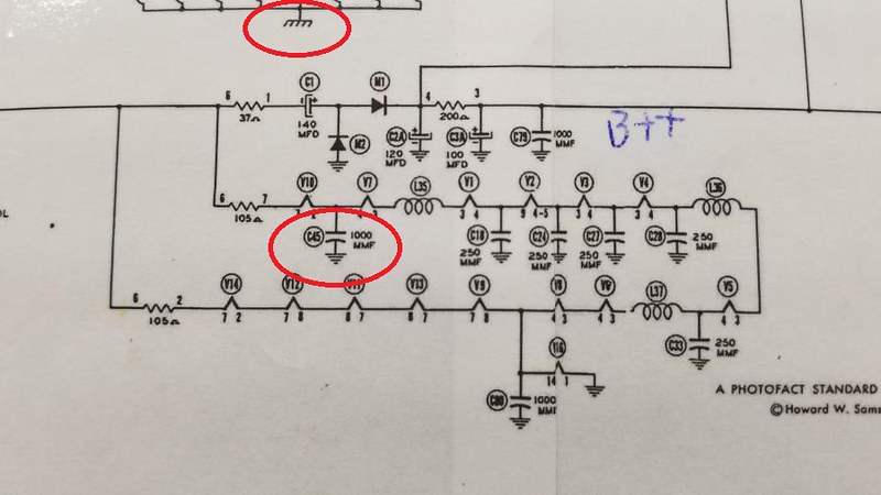
I noticed that C-45 in the Sams schematic you posted does not match the Motorola factory issued schematic for a TS-4J late model. The ground end of C-45 should be connected to the floating B- line, not chassis ground. Also if you are using an original metal can ballast, make sure that it does not have any internal shorts. Remove the ballast if you have to, and check the pins for proper continuity and resistance. Your set is supposed to use the latter ballast, as shown in the schematic you posted. A ballast with internal shorts will cause all kinds of problems.
Ed
|
|
#28
07-17-2018, 08:59 AM
|
||||
|
||||
|
C-45 in the Sams is going to B-. B- is represented by the taper horizontal line symbol. Chassis is represented by the symbol with diagonal lines I circled at the top.
|
|
#29
07-17-2018, 09:19 AM
|
||||
|
||||
|
Quote:
Quote:
I can't check it today, (Adding a new rack to the workbench) but I'm almost positive I connected the output of the capacitors directly to the chassis. This whole floating chassis thing is a real pain in the neck.
__________________
"If it isn't broke, you aren't trying hard enough"
|
|
#30
07-17-2018, 09:35 AM
|
||||
|
||||
|
Definitely do not connect anything to the chassis.
Quote:
Ah, that's weird. What caps do you mean exactly? There are two electrolytics in the audio circuit and neither goes to B++. If you mean the 20uF cathode bypass on the audio output tube, it should only have about 9 volts across it. Perhaps that 25L6 has a short or is miss wired ? The other is a 10uF in the FM ratio detector that should only have a few volts across it as well.
|
| Audiokarma |
 |
|
|


 Linear Mode

