
|
|
|
#1
 12-30-2023, 04:25 PM
|
|||
|
|||
|
3-D Printing Missing/Broken Parts?
Has anyone done this for vintage TV parts or make custom brackets etc for your work from 3-D printing? I just got a decent resin bath unit. Didnt want the filament version. I love RCA 14 and 17 inch sets from the mid to late 1950s but so many times, the cover on the back of the yoke that holds the centering magnets is baked beyond saving and often crumbles into powder on contact. I want to create these and a few other parts.

|
|
#2
12-31-2023, 12:22 PM
|
||||
|
||||
|
I 3D printed a face mask for a 5 inch TT5. I did it in 2 parts; one for the out facing mask and the 2nd for the piece that holds the CRT. I printed fasteners for metal shelf poles which used real metal bolts. I made a custom fastener to hold a 17 inch LCD TV on one of the metal poles which I used as a 2nd monitor for Windows but the fastener broke after a year. Also the fastener broke on one of the ones holding 2 poles together. I used a cheep padlock from the dollar store which replaced it. I 3d Printer a couple TV channel selectors. I 3d printed some bolts and nuts but found they broke easily. I 3d printed a holder for an action cam which also had one piece break. I use PLA filament. Most of the stuff the broke had a thickness under 1/8 of an inch. The TV mask is about 1/4 inch and is pretty strong. I took a local free class about 5 years ago where the instructor built a rocket in class. It was built in stages with each piece fitting together like a vacuum cleaner tube. I printed a box with a lid which fit over the box. I 3d printed a Kraft TV show 1/3 size cameraman. It took several tries to get the camera overhang to not fall off. I printed it in one piece so the wheels didn't turn or the cameraman swivel on the cart. I printed a sprocket for the ships wheel on a Western Visionette mechanical TV. I didn't have the screw threads on the end so it has to be stuck in versus the ability to screw in/out. I purchased a cheap CNC for $200 but paid $300 more for software which allows carving on 4 sides. In my case I have to manually flip the object. I could buy a rotisserie spindle which my software supports but then that would add another layer of cost. I good thing about CNC is that drill bit are sold with many angles 15 degrees to 90+ degrees so the bit does the angles versus your design. ie. inside of a TV mask in the software is a simple like in a circular type curve but the drill bit can make it 45 degrees routed all around the edge.
|
|
#3
12-31-2023, 04:04 PM
|
|||
|
|||
|
Quote:
|
|
#4
12-31-2023, 04:27 PM
|
||||
|
||||
|
Top of photo attached show using a "V" drill bit on CNC for a beveled angle Bottom shows 3D printed beveled angle.
I had a hell of a time designing a beveled angle using 3D printing software. There's probably an easy way to do it. For my use I found making a solid like a cone and doing a Bollean difference with a square is one way of creating beveled edge on inside like a TV mask. This is Similar in construct to creating a mold. I've thought for TV knobs it might be easier to 3D print a mold then pour resin into the mold and then do the back of the knob part in the mold. I use free software: Meshlab, Meshmixer, Blender and some free online Cad program such as tinker CAD. I also use some 3D scanning software.
|
|
#5
01-01-2024, 01:03 PM
|
||||
|
||||
|
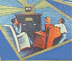
Photo of 3D model of Pilot TV face. The color rendering on the top makes it look better then it is. The bottom is the same model just not rendered with color. This was created with multiple camera picture scans of a pilot TV. It could be improved by replacing each horizontal bar in the software and redoing each knob in detail and then replacing the current knobs in the model with the new ones. You could take a new picture of the front face or use this photo as a template to create a new model from scratch. There are dozens of ways to create a model i.e. CAD program, Mesh program, Art program, Scan program. etc Within these programs you can use additive or subtractive constructs
|
| Audiokarma |
|
#6
01-01-2024, 03:48 PM
|
||||
|
||||
|
For those not familiar with creating 3D objects. Additive is merging two objects. Subtractive is removing a piece of an object. In the attached jpeg photo (from TinkerCAD) in #1 a rectangular cube has the front edges removed creating beveled front end. This can be accomplish by performing a boolean difference command with a 2nd cube at angle to the 1st cube. Also in #1 you see large small diameter cylinders to be used as vehicle axles. On the front end is 3 rectangular cubes joined as a "U" shaped figure. In figure #2 wheel shaped objects are added. The wheels can be made by taking a cylinder and subtracting a smaller cylinder shaped object then subtracting a smaller cyliner shaped object so the wheels will slide on the axle shafts created in #1. #3 a tail fin is added. Body fenders are added constructed out of cone shapes. #4 more cone shapes added. Some 3D software uses mesh objects (usually made of thousands of triangles). Others use more of a solid object (Nurbs, Pucky Balls or Blobs). Meshlab, Meshmaker uses meshes. Rhinosceros uses Nurbs. Some older packages from the 1980s used pucky balls or blobs. Think of creating a snowman figure by sticking together snow balls. If you want moving parts it might be better to use a CAD program. If your making a figure, scupture or statue (dog, horse, head of a person, totem pole etc) you might find an art oriented software more to your liking.
Last edited by rld-tv01; 01-01-2024 at 03:53 PM.
|
|
#7
01-03-2024, 10:29 AM
|
||||
|
||||
|
In the immediate post above I was thinking in Mesh terminology. In #1 figure the body of the vehicle could be constructed with a CAD program as an object without cutting off sections as described using Boolean difference. Also there might be an operation where you can provide the parameters of an object. i.e. the number and lengths of the sides. The dimension of the front and dimension of rear i.e. 1 inch by 1 inch (front) to 3 inch by 3 inch (rear). I have mainly used mesh packages but if you need accuracy and precision i.e. pistons in an engine then CAD "Computer aided Design" would be the choice. For a toy car as in the example you could use whatever approach you wanted. The bottom line you you have many choices for design and the right one depends on your needs and goals.
|
|
#8
01-03-2024, 12:05 PM
|
|||
|
|||
|
Quote:
|
|
#9
01-03-2024, 07:21 PM
|
||||
|
||||
|
For CAD I mainly used SketchUp when it used to be free and PC based versus web based. I also purchased Rhinosceros 1.0 years ago and PCs seemed underpowered at the time for running it. I recently tried Tinker CAD which is free (online use). It's function seems similar to SketchUp. I purchased Agisoft Metashape years ago for 3D scanning objects using a 35 MM camera. it's 3D object output (STL or OBJ) was more in line with Meshlab and Meshmixer. I haven't used FreeCAD or Fusion360. I have an Inventables userID which is a package tailored more for CNC. They sell have high end software called Easel. I purchased DeskProto software for my CNC. It allows importing standard 3D STL files and then builds a custom workflow toolpath for CNC. Deskproto allows manual flipping the piece of wood or using an auto rotational mechanism. I like Meshlab but use Meshmixer to analyze and fix problems. Meshlab requires a list of a dozen commands to fix object errors while Meshmixer does it graphically with graphical pinheads pointing at each problem area. You select the pinhead pointing at a hole etc with your mouse then push the fix button. It also has a fix all but it gives undesirable results. Meshmixer also has a undo cntl Z facility.
|
|
#10
01-04-2024, 01:18 PM
|
||||
|
||||
|
Back last July another user VideoKarma use Resonance1 was looking for some phtos of knobs for Admiral 30A12 TV
http://videokarma.org/showthread.php?t=275980 I tried TinkerCad (free online web access) for the first time and created an initial 3D model of one of the knobs. I never finished the model but here is a snapshot of my admiral knob from my TV and the model I created with TinkerCad Basically a cylinder resized and Rectangular box containing subdivisions. I created the 3 boxes across then created a duplicate and joined the two together. It was series of copies and joins. As I stated it was not finished. It could be created several ways. It seems TinkerCad mechanism for creating is similar to a mesh package such as Meshlab and Meshmixer. I didn't do any geometry. Maybe Resonance1 or others can give thoughts in a better way forward. Autodesk TinkerCad is free. All you have to do is create an online ID and start creating. https://www.tinkercad.com/
|
| Audiokarma |
|
#11
01-05-2024, 04:26 PM
|
||||
|
||||
|
One way of many to create the Admiral knob. See attached photo.
Drag top right cube onto desktop and resize to rectangular cube on workspace (red right cube). You have a choice of Solid or Hole; select solid. Drag another cube to desktop, resize and select hole. The cube in front of the small red one with a texture like the hole pattern. When you arrange the first solid rectangular cube with the 2nd which is a hole, you get a cube with a small hole in it. Make 3 holes across. You can now duplicate the rectangular cube with the 3 holes and attached them together. Repeat the require number of 3 holes then you need a section with holes on the side and center a hole crossing several holes on the side. When you have the knob pointer structure complete (large red structure on left) you can resize the dimensions as needed. If the holes you made are too deep you can drag in another cube (orange one) resize shorter in height then the red one. Combine the two which will make the holes more shallow. Note to finalize making a hole or joining you need to select both object (drag around the two object to select both of them). Then select the group button to finalize. See creating hole tutorial youtube video. https://www.youtube.com/watch?v=IxrsHSELHsw Last edited by rld-tv01; 01-05-2024 at 05:13 PM.
|
|
#12
01-07-2024, 06:21 PM
|
||||
|
||||
|
You might haven noticed the admiral pointer on the knob is not a straight rectangular cubic but have a curved arch. There is a youtube video showing how to take coral draw to engineer a complex curve and importing into TinkerCad. I used a similar approach but used MS Paint to create an outline of a solid object. The MS Paint drawing is of the side of the object (2D drawing). You can stretch the width later after it's an STL. I then used online program https://imagetostl.com/convert/file/jpg/to/stl to convert the JPG to an STL. The default is the object needs to be white with a black background. After creating you download the curved object so you can upload to TinkerCad, Meshmixer or other program.
The attached file shows: Blue pointer - as produced by JPG to STL Grey Pointer - Blue pointer smoothed by Meshmixer Red pointer - I took the yellow half cylinder; cut it in half with a cube hole; stretched the part across a rectangular cubic for left 2/3rds and used a 2nd cubic for the remaining right side. 3 parts total: The yellow object was stretched and sized to create the top left of the red pointer. Cubic across the bottom and a cubic on right. The parts were all sized, aligned and grouped. Last edited by rld-tv01; 01-07-2024 at 06:26 PM.
|
 |
|
|


 Linear Mode

