
|
|
|
|
|
#1
 07-16-2018, 09:28 AM
|
||||
|
||||
|
The filament circuit should not be affected for the caps. There are two series filament strings that connect directly to the AC line through a ballast resistor.
Sounds like there is a problem in the voltage double B++ supply that is shorting out the AC line. Note that none of the negative leads of the electrolytics connect to the chassis. The chassis is floating in this set - it is not common. Also make sure your diodes are not installed backwards. Also I'm wondering about the values of the caps you're using. There should be a 140, 120 and 100 uF cap in the B++ supply circuit - nothing in the 10-20 range. 
|
|
#2
07-16-2018, 01:29 PM
|
||||
|
||||
|
There are 2 smaller caps in the circuit not the power supply so if they are going bad then it almost sounds like ac is getting into the DC circuit. I would stop and go over the schematic with a fine tooth comb and start at the diodes as bandersen noted that the b- does not go to the chassis at all. If the diodes were backwards you may get nothing but if one is backwards then you would have a problem, sort of maybe having DC on one side and ac on the other which should not be. The filiment string should not be dependant on an electrolytic cap the ac would distroy the cap . If it were then as soon as the cap takes a dump so does the filiment string, goes out.

|
|
#3
07-17-2018, 01:13 AM
|
|||
|
|||
|
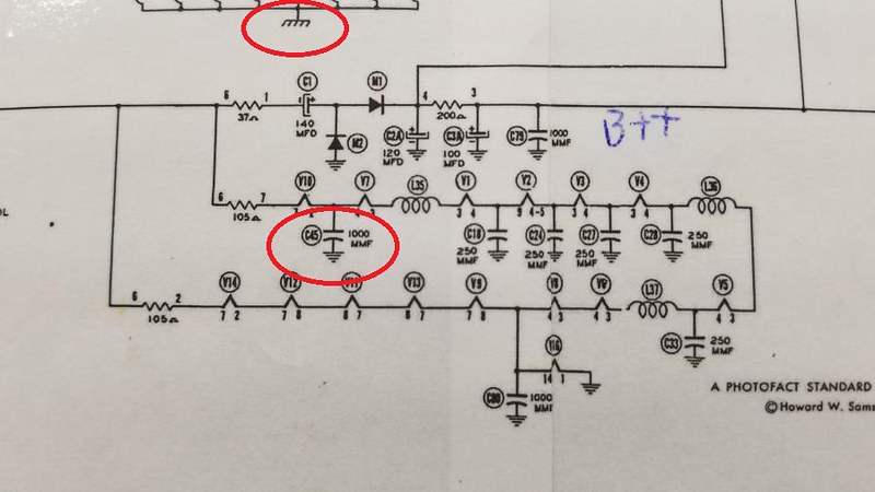
I noticed that C-45 in the Sams schematic you posted does not match the Motorola factory issued schematic for a TS-4J late model. The ground end of C-45 should be connected to the floating B- line, not chassis ground. Also if you are using an original metal can ballast, make sure that it does not have any internal shorts. Remove the ballast if you have to, and check the pins for proper continuity and resistance. Your set is supposed to use the latter ballast, as shown in the schematic you posted. A ballast with internal shorts will cause all kinds of problems.
Ed
|
|
#4
07-17-2018, 09:19 AM
|
||||
|
||||
|
Quote:
Quote:
I can't check it today, (Adding a new rack to the workbench) but I'm almost positive I connected the output of the capacitors directly to the chassis. This whole floating chassis thing is a real pain in the neck.
__________________
"If it isn't broke, you aren't trying hard enough"
|
|
#5
07-17-2018, 09:35 AM
|
||||
|
||||
|
Definitely do not connect anything to the chassis.
Quote:
Ah, that's weird. What caps do you mean exactly? There are two electrolytics in the audio circuit and neither goes to B++. If you mean the 20uF cathode bypass on the audio output tube, it should only have about 9 volts across it. Perhaps that 25L6 has a short or is miss wired ? The other is a 10uF in the FM ratio detector that should only have a few volts across it as well.
|
| Audiokarma |
|
#6
07-17-2018, 08:59 AM
|
||||
|
||||
|
C-45 in the Sams is going to B-. B- is represented by the taper horizontal line symbol. Chassis is represented by the symbol with diagonal lines I circled at the top.
|
|
#7
07-18-2018, 01:30 AM
|
|||
|
|||
|
Quote:
Ed I did some more checking today, it seems the ETF Riders schematic for the TS-4J is for the early version. I added a picture of the schematic for the late version power and filament supply. Last edited by EdKozk2; 07-18-2018 at 07:03 PM. Reason: More info
|
|
#9
07-19-2018, 11:12 AM
|
||||
|
||||
|
Quote:
Quote:
__________________
"If it isn't broke, you aren't trying hard enough" Last edited by Zsuttle; 07-19-2018 at 11:26 AM.
|
|
#10
07-19-2018, 02:21 PM
|
||||
|
||||
|
You can download Motorola service info from the Early TV Foundation here: http://www.earlytelevision.org/tv_sc..._motorola.html
I belivebe the only mistake with the Sams is showing some of the filament bypass caps going to B- when they should be the chassis. They changed the ballast tube and the contrast control circuit from the early to late TS-4J. There may be other very minor differences. The power supply circuit is the same.
|
| Audiokarma |
|
#11
07-20-2018, 11:41 PM
|
||||
|
||||
|
Alright, I've gone over the schematic with a fine tooth comb and determined that every component is in its proper place. (I'll give it to Motorola to make things difficult) Both diodes were installed correctly and the same with all of the caps. Any advice?
__________________
"If it isn't broke, you aren't trying hard enough"
|
|
#12
07-21-2018, 04:57 AM
|
||||
|
||||
|
Quote:
|
|
#13
07-21-2018, 10:18 AM
|
||||
|
||||
|
Another thing to beware is heater to cathode shorts...
Also, you are sure your diodes are installed correctly, right?... May want to double check with a DMM in DC volts mode connected between B++ and B- during power up...
__________________
Tom C. Zenith: The quality stays in EVEN after the name falls off! What I want. --> http://www.videokarma.org/showpost.p...62&postcount=4
|
|
#14
07-21-2018, 03:03 PM
|
||||
|
||||
|
It may also be worth checking to chassis ground because who knows what was done to the chassis already and what may have been bad or shorted out already like possibly the filiment caps to ground or maybe a carbonized .470 resistor to chassis. It is a stretch but being the problem is becoming a headache, why not.
|
|
#15
07-29-2018, 04:14 PM
|
||||
|
||||
|
Well I can definitely confirm that some of the caps going to chassis have shorted. Curious, because on my meter they still show the proper capacitance, however the resistance is just a few ohms. I think this could be the issue causing the diodes to blow. Still on vacation, once I return Ill be able to tell if thats been the only problem.
Cheers, Zach
__________________
"If it isn't broke, you aren't trying hard enough"
|
| Audiokarma |
 |
|
|


 Hybrid Mode
