
|
|
|
|
Thread Tools | Display Modes |
|
#1
 01-18-2016, 05:36 PM
|
||||
|
||||
|
How to repair a Mallory inductuner (Dumont RA-103, and clones) with a broken shaft
Since I can't find a thread on this anywhere, and I had to teach my self how to do this with only pictures of good tuners to go by I figure I may as well share what I've learned with anyone who may be interested.
As some of you know a few months ago I got a Dumont RA-103 Doghouse (more like a mouse house) with a broken ceramic tuner shaft, and a Stromberg Carlson TV-10 (a TV-12 with a smaller CRT) which is a RA-103 clone (it's tuner is completely missing the ceramic portion of the tuner shaft). The following advice applies to all the above and other sets that use the same tuner as the RA-103 (such as the Crosley 9-407). I restored the chassis on the TV-10 first (since as a whole it was in better shape). Since it's tuner was missing too much to be repaired I harvested the broken tuner off the Dumont and rebuilt it. It comes off by removing 3 wires on the front (I recommend removing the dial scales for better/safer access), 1 wire under the chassis, the lead to the antenna terminals, and 5 screws under chassis.  DSCN1301 by Tom Carlson, on Flickr DSCN1301 by Tom Carlson, on Flickr  The top cover was already open with the top 4 of it's 8 screws removed and it peeled back so I could see in. The shaft had broken cleanly aside from a small notch on one side, on both sides of the break. All three sliding coil contacts were off track but present, and there were several small ball bearings at the front. Even if they were missing I had/have a hopeless parts tuner on hand as a fallback/donor. I first made a partially incorrect guess as to where the bearings came from. I assumed they were from the spot where the knob portion of the shaft left the front of the tuner, which they were part of, but I did not put them in the correct spot on it (which I'll later elaborate on). After installing the bearings wrong I lubricated them and the concentirc brass rotational stops made a brace to hold the bearings in by holding the shaft forward, cleaned the shaft on both sides of the brake (not thoroughly enough) with "Goof-Off" and cleaned the contacts.   I then glued the ceramic shaft back together at the break using "Super Glue" and after that dried wrapped the surrounding shaft in 2 part epoxy to add strength, and reassembled the shaft on to it's adjustable rear pivot screw.    All seemed good until I gave the user end of the shaft the wiggle test. It had WAY too much play. I could easily un-mesh the gear on the shaft from the reduction gear for the inner rotating dial scale (which should not happen) by pushing the shaft up. Well I went and consulted the user shaft remnant on the ruined spare tuner and after coaxing a bearing or two out of it I could tell it's likely original bearing pack was different from mine. I had to spend $10 on a hex set to get the 1/20" (0.05mm) hex key to remove the front gear to be able to pull the shaft far enough out to repack the bearing properly. There are 9 balls in one from what I can tell, and it is recommended that the tuner shaft and tuner be facing down while packing the bearing. The below graphic of the removed shaft illustrates where the balls should go, and the incorrect place I initially placed them.    After repacking the bearings I proceeded to remount the shaft. I tightened the rear pivot screw down to 11 to try and reduce some residual shaft wiggle resulting in some squeaking when turning. The dial gears no longer seemed able to un-mesh so I installed the sliders and dial scales. And after some playing with the mechanism it became clear that I had not glued it perfectly straight and at some spots in the rotation the gears would un-mesh, but if I pushed down on the shaft it would keep the gears in mesh. At this point I mounted the tuner on the chassis and tested it out. It worked well for 3 sweeps through the tune-able range but on the third the tuner died....I opened it up and found the sliders had hopped out, the super glue had busted and the epoxy was BARELY holding the shaft together (allowing the sliders to pop out). At that point I waved a hammer over the tuner sub-chassis (miming out the destruction a overruled part of me wanted to dish out), and went to bed.    The next day I chipped/dissolved off the epoxy and glue with a small screw driver and "Goof Off"...Some of it came off too easy indicating I had not removed all slippery goo and dirt from the surfaces the first time. I then proceeded to re-do the process only this time with the tuner shaft totally removed, and was able to get it glued straighter (still not perfect). I did not over tighten the rear pivot this time, and since it is straighter there is no longer any problem with gear mesh, and thus I no longer have to push down on the tuner shaft (which ruined the first glue job). I also cleaned the tuner more thoroughly with "Goof Off" which got a surprising amount of dirt out of the seemingly clean coils, and also remover the stubborn dirt in the slider tracks (had to replace a slider that I broke the insulator on too). 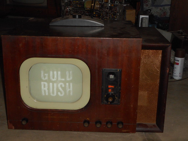 DSCN1333 by Tom Carlson, on Flickr DSCN1333 by Tom Carlson, on FlickrThis time it works and shows no signs of fault or relapse, and I can turn the shaft EASILY without putting any of the dangerous non-rotational forces that re-ruined it before. I'm now confident enough in my process that I feel I can repeat it for any tuner in similar condition to that which I got mine in. Additional processes worth explaining: Dial alignment: With the tuner shaft cranked all the way clockwise put the dark dial scale on with ch13 at the 12-o'clock position, and then put the clear dial scale on with it's ch13 aligned with the other scale's ch13 at the 12-o'clock position. Slider installation: Turn shaft and observe any vertical undulation from rotation if there is any noticeable amount (or a slider likes to pop out regularly) pinch the contact ears of the slider closer together to increase force of their spring grip. Then, while watching the coils from the top, rotate shaft to it's stop (note which direction each wire moves as it's rotated). Take a slider and press it's ears against the last turn of wire on the end of the coil the direction the wire was moving towards when turned. Once the ears are seated on the last turn keep them there and rotate the slider on the coil (or with the coil if it's easier for you) underneath til it is wedged on the beginning of the metal part that contains the slider contact track, then use a small screw driver to push it in til it seats in it's track groove. Rinse and repeat for the next two sliders. If it pops out when rotated to the other end of the coil you did not seat the slider on the right turn of coil or other things are wrong.
__________________
Tom C. Zenith: The quality stays in EVEN after the name falls off! What I want. --> http://www.videokarma.org/showpost.p...62&postcount=4 
|
|
|


 Threaded Mode