
|
|
|
#1
 12-06-2008, 12:00 PM
|
||||
|
||||
|
A few restoration questions-- rectificiation, B+ voltage, etc
Hi Everyone,
I'm pretty new in here. I was recently given a Zenith tube radio, a C845, chassis 8C02. I have been trying to teach myself enough to get it operating safely (I have done some soldering and worked on low voltage circuits before), and have a capacitor kit here to replace the electrolytics, but I have a few remaining questions and searching the internet isn't yielding the information I need. I hope some of you guys can help a newbie get it right (and avoid killing himself). Bear with me, these are going to be some pretty basic questions! 1. How do these radios step up the voltage (B+) that is used for the tubes? The radio I have uses a selenium rectifier. I have the schematic, but I can't tell what the output voltage should be (the first voltage shown after the rectifier and a subsequent resistor is 120v, but I don't know if this should be my target, or for that matter how 115v mains on the schematic becomes 120v after rectification). 2. How do I test B+ voltage? I have an old analog multimeter-- where would I clip both leads? Guidance here would be especially appreciated, as I think this is probably the most dangerous thing I will do) 3. I have a IN40007 diode to replace the selenium, but I'm a little confused about how to know what step down resistor to use. I think I'm supposed to be able to measure the B+ voltage coming out of the diode and calculate the appropriate resistor value to get it to the appropriate level (if I could figure out what that should be). Am I on the right track here? 4. Someone from another posting on this radio recommended using a 68 ohm, 5 watt dropping resistor. The local neighborhood Radio Shack doesn't stock anything this beefy--would I need to order something like this, or can I put some power resistors in series until I get the correct B+? Thanks in advance for any information you might have-- I would really love to get this radio running, but teaching myself tube circuits is harder than I thought! 
|
|
#2
12-06-2008, 12:46 PM
|
||||
|
||||
|
Hi, I don't have the schematic and can't find it on Nostalgia Air, but this sounds like a typical four or five-tube AC/DC radio? When you install your 1N4007 diode, the band (cathode) on the diode goes towards B+: think of the B+ flowing out of the diode on the band end. You can use almost any resistor from 50 to 100 ohms, 1 or 2 watts should be OK, in series with the diode. When you install your electrolytics, be sure to disconnect the old ones as they can go (or maybe already are) shorted. Check how the new electrolytics are labeled because sometimes they can be confusing. They may have a stripe down the side with minuses on it, pointing to the negative end. The negative end will be the aluminum "can" of the cap, usually visible where the wire comes out. The positive end will have an insulating disc that the wire emerges from. Install exactly as the old ones were installed electrically.
It is recommended to replace all the paper caps in the radio with new caps. To test B+ : set your meter to cover 120 volts DC, which may be the 200 volt setting? After your new 1N4007 and new resistor, there will be a filter cap, another resistor, and the last filter cap. Put your meter's positive lead on the + side of the last filter cap. Put the negative lead on the common point where the negatives of these filter caps come together. This point would also be the negative point for any other DC voltages on the chassis that you want to check. It would be good to use clip leads for this so you aren't "in there" with a live set. This is probably a "hot chassis" radio so you want to have sneakers on and a rubber mat on the floor, and don't touch the chassis while it's on unless you're insulated from ground. Good idea to keep one hand in your back pocket to avoid making a closed circuit! (Old radioman's trick. That's how they got to be old.) If you have a variac, bring the set up slowly and watch for any signs of overheating or smoke (heaven forbid!) from any resistors, etc. Around 90 volts or so you should hear some crackles from the speaker, and it may begin to play. If you don't have a variac, put a lamp socket in series with the power cord. Screw in a 60 or 70 watt lamp (incandescent bulb) and watch for untoward signs from the radio. Then go to 100 watt. Radio may start playing. If all is OK with 100 watt bulb, then plug the radio in normally. I would not worry about getting the B+ exactly per the schematic: radio will work with the B+ probably within 10% of it. The filters store up some juice so that's why the voltage can appear higher than line. No reason why you can't use several resistors in series to attain the value you need. Just need to have room for them and proper support and ventilation. You would find it easier to mount all these parts by adding a several-terminal solder-lug type terminal strip under the chassis. Best of luck to you, and Stay Insulated! Reece
__________________
Reece Perfection is hard to reach with a screwdriver.
|
|
#3
12-07-2008, 10:34 AM
|
||||
|
||||
|
The schematic is online here: http://techpreservation.dyndns.org/s...ics/Zenith.htm
You'll need to get the DjVu plug-in or IRFANVIEW with its DjVu plug-in to open it. http://www.celartem.com/en/download/djvu.asp No need to add a resistor - the tubes will take the extra voltage from a silicon rectifier just fine (though some radios need a bit more caution... battery / AC ones especially)
|
|
#4
12-07-2008, 02:28 PM
|
||||
|
||||
|
Quote:
Thanks! Dan
|
|
#6
12-10-2008, 12:17 AM
|
||||
|
||||
|
Quote:
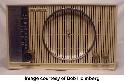
The C845 is an eight-tube radio with a two-way speaker system. It also has an RF amplifier that works on both bands and two IF stages on both AM and FM as well (actually, the set also has a limiter stage which counts as a third IF amp). This all makes for a radio that is extremely sensitive on both bands, simply using its built-in Wavemagnet AM antenna and line-cord FM antenna; the latter is connected to the external FM antenna terminal by means of a short wire with a spade lug at one end, but the actual coupling to the line cord is done with a clip around the cord, which cannot be seen unless the back is removed. This works the same way as the usual line-cord antenna arrangement on other Zeniths, including the K731; these also use a clip around the cord that connects to the FM antenna terminal, but the clip is plainly visible on the back of the set. The sound quality of the C845 is excellent. I have one and was (still am) very pleased with the sound, especially the deep bass from the 8" main speaker. The 5" tweeter in the C845 is a true loudspeaker, not an electrostatic tweeter as is used in the K731 and others in the 800 series as well (some versions use two of the latter, one on either side of the main speaker; my 731 only has one), but it still delivers very good response for the higher frequencies. It can be difficult to tell if the tweeter is actually working in either the 800-series Zeniths or the K731s unless the main driver is temporarily disconnected. I did just that with my K731 when I had it apart for maintenance recently; the tweeter works, and well, but I had to increase the volume quite a bit to hear any output from it. All in all, the C845 and probably every other radio in Zenith's 800 series are great sets, delivering very good sound and having excellent RF sensitivity. There is ordinarily no need to use external antennas with these radios in most areas; the RF stage ahead of the built-in antennas, combined with what amounts to three IF stages on both bands (thanks to the limiter stage), means you will have excellent reception wherever you are. As others have mentioned, these sets will receive stations most modern radios don't know are there, and of course the sound quality is fantastic, comparable to a Bose Wave radio/CD system, again as has been noted at least once in this forum. These radios were made when Zenith's longtime slogan "the quality goes in before the name goes on" actually meant something.
__________________
Jeff, WB8NHV Collecting, restoring and enjoying vintage Zenith radios since 2002 Zenith. Gone, but not forgotten.
|
|
#8
12-10-2008, 01:22 PM
|
||||
|
||||
|
Quote:
How those power supplies output a higher voltage than was seemingly fed into them was a mystery to me for many years until someone finally explained it in a way I could understand. I'll try to paraphrase their explanation here. The actual value of an AC voltage is constantly changing. For example, 110 volt AC actually means 110 volts RMS. That means that the average voltage of the constantly changing AC waveform is equivalent to 110 volts DC. Sometimes it's less, sometimes it's more. Sometimes it's zero volts and sometimes, it's at its peak voltage, at the top of the sine wave. The RMS voltage of a sine wave is equal to 0.707 it's peak voltage. A little math (or a peak reading meter) tells you that the highest voltage reached by the waveform of a 110 volt RMS sine wave (and only for an instant in time) is about 165 volts. The waveform spend it's time varying between 0 volts and 165 volts and it's average voltage equal about 110 volts. When you convert that voltage to DC with a rectifier and feed it to a filter network, the capacitor in the filter network begins to charge from the DC which is pulsating between zero volts and 165 volts. If you drew no current from the power supply, the filter capacitor would quiclky charge to the peak value of the fluctuating DC feeding into it. When you operate the circuit, you load the power supply by drawing current. The less current you draw, the less the filter capacitor "gives up" to the load (and the better it filters out the ups and downs of the pulsating DC!) The more current you draw, the more the capacitor has to empty to feed the load. If the circuit is designed so that the load is fairly light compared to the storage capacity of the filter network and the ability of the rectifier to resupply it, then the capacitors will spend more time charging than discharging and will be able to charge to - and maintain - a higher voltage than if the load is drawing more heavily. If the load is greater, the output voltage will be lower since the filter capacitors must discharge to a lower level to feed current into the load. Since they are being fed with only a certain amount of power they don't get a chance to charge back up past a certain voltage level. This charge/discharge situation almost instantly reaches equilibrium at whatever DC output voltage the supply vs. load balances at. The circuit will be designed to achieve the desired DC B+ level with the intended load. That can be up to 165 volts for very light loads, but will never actually reach that level even with no load due to circuit losses. Clear as mud? There are tutorials on the web that probably explain this better than I can. Good luck, --Dave
|
 |
|
|








 Linear Mode

