
|
|
|
#1
 04-24-2010, 05:23 PM
|
||||
|
||||
|
Re-installing Zenith Roundie Chassis rebuilt by Doug
I decided to finally re-install the chassis that Doug rebuilt for me some months ago.
  All went well until I came to the degauss coil wiring... It appears I did write down that it came from a connection strip with 5 "prongs", the last two being for the degauss coil. Problem is, there are many strips that fit that description, and I drew it horizontally, but the strip I "think" it came from is vertical!  Can someone tell me where (physically) the coil is supposed to plug into? I think this is Chassis 24NC32 (although I could be off, it's not in front of me right now) At any rate, this is the one we all know is Zenith's last roundie chassis from 1967 or such... Thankee
__________________
From Captain Video, 1/4/2007 "It seems that Italian people are very prone to preserve antique stuff." 
|
|
#2
04-24-2010, 06:35 PM
|
||||
|
||||
|
If it's the 23MC32 chassis (H.S. 804-4) you may want to look under the chassis to verify. The input lead would be off the circuit breaker and the other point would be at the junction of the B+ diodes.
I don't have a chassis to compare but just the sams.
|
|
#3
04-24-2010, 06:43 PM
|
||||
|
||||
|
I just double checked, this is chassis 24NC31Z.
No circuit breaker on this one. Thanks anyways 
__________________
From Captain Video, 1/4/2007 "It seems that Italian people are very prone to preserve antique stuff."
|
|
#4
04-24-2010, 08:04 PM
|
||||
|
||||
|
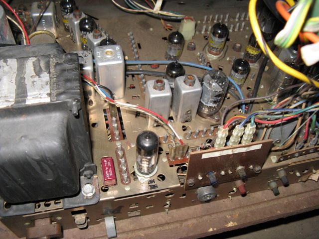
Those plug into first two pins directly to the right of the 12HL7 video output tube as shown here. The chassis on mine is marked "DGS" with a grease crayon, probably done at the factory. I've seen others like yours with no markings at all.
__________________
I tolerate the present by living in the past... To see drh4683's photo page, click here To see drh4683's youtube page, click here
|
|
#5
04-26-2010, 04:47 PM
|
||||
|
||||
|
Best thing to do is use that digital camera before removing anything, so you know how it all goes back. I do the same for all stuff like that just in case a soldered wire on some terminal strip comes off, even in an area I'm not working in..... Just shoot everything top and bottom. It don't cost anything and you can delete them when nothing goes wrong. Do it in addition to making a map on paper when removing several parts, Electrolytics, etc.
__________________
Yes you can call me "Squirrel boy"
|
| Audiokarma |
|
#6
04-26-2010, 08:27 PM
|
||||
|
||||
|
Quote:
But on the real... Thanks for the photo Doug... Plugged it in and I was in business! As has been said before on this forum recently,  I was really surprised and glad to see that even though chassis and CRT have been in different states and apart for many years, it doesn't appear I'll have to do much in the way of convergence, gun balance, etc. Pretty much has a good picture the minute I plugged it in. Here is a rather snowy channel 9 (Canada) which is not the best in basements on cheap rabbit ears:  Hockey games (mostly white ice) also not the best for showing off color! Now on to the problems... Cannot get channel 3 to tune in my digital box! It's right on the edge of wormyness and buzz:  Spun the fine tuning quite aways in each direction to no avail. When switched to channel 2, it's much better, but with bad sound...  Fine tuning does affect the picture, so I know it's engaged and functioning. However it seems the proper setting is just out of range. Channel 9 and low power UHF stations are also normal. I did try a little AGC tweak with no meaningful effect. My main fear is tuning "too much" and really throwing channel 3 out of range. Your thoughts? Here is a screen shot back in the good ol' days of analog, so you know it's a typical Zenith in terms of picture quality... 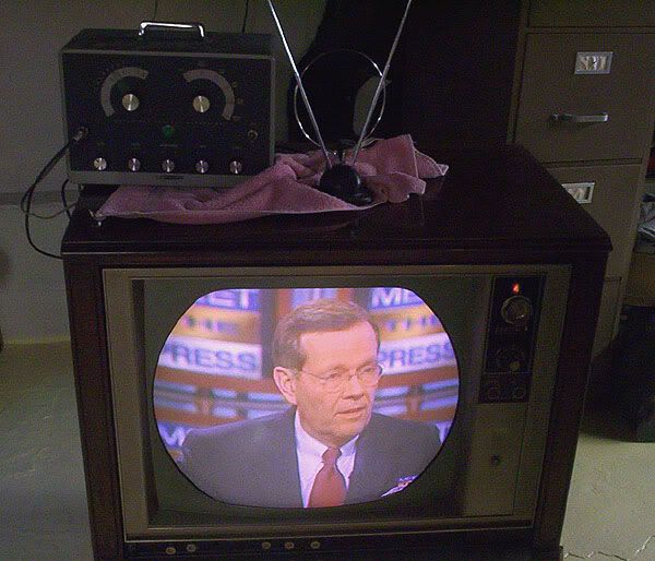
__________________
From Captain Video, 1/4/2007 "It seems that Italian people are very prone to preserve antique stuff."
|
|
#7
04-26-2010, 09:49 PM
|
||||
|
||||
|
The trouble is in the tuner, which I never had so I couldn't check it out. It appears that the mixer oscillator isn't on the right freqency. Change out the 6GJ7 in the tuner, that should bring the set back to normal. Glad its working out.
__________________
I tolerate the present by living in the past... To see drh4683's photo page, click here To see drh4683's youtube page, click here
|
 |
|
|


 Linear Mode

