Videokarma.org

Go Back   Videokarma.org TV - Video - Vintage Television & Radio Forums > Early B&W and Projection TV

Notices

We appreciate your help

in keeping this site going.
Reply
 
Thread Tools Display Modes
  #91  
Old 02-12-2012, 03:11 PM
earlyfilm's Avatar
earlyfilm earlyfilm is offline
Eternal Member
 
Join Date: Jun 2011
Location: Culpeper, VA
Posts: 527
Quote:
Originally Posted by vts1134 View Post
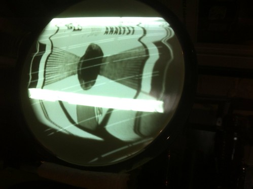
. . . . . . I had prevously thought that the vertical was running too slowly but you can see now that is not the case. The horizontal white bands do not roll with this signal, instead they are steady right where you see them.


VTS1134,

OldCoot is suspecting one problem, and he very well may be correct.

Let's stop and think about the problem.

I see the vertical section attempting to run at 120 cps and it is badly speed modulating the sweep resulting in dual white bands. In other words, the normal 60 cps sawtooth is being speed modulated by a two backwards steps at a frequency of 120 cps.

The wrong speed operation could be caused by either a 120 cycle hum being fed to it from the power supply or from some component in the vert osc/output circuit being badly off value. (A heater cathode short would introduce a single band. Only the 120 cps hum can create a double band and 120 usually is only found in a full wave power supply.)

1) I assume that you do not have a service scope. If you do, the first thing to check is the B+ and B- power supply sources for hum. Then check to see if the waveforms from the sync separator through the vertical output are correct.

2) Substitute the vertical tube. If you don't have a spare, switch the video output 6SN7 with the vertical output 6SN7 tube. If this changes your problem, then you probably have a bad vertical output tube.

3) Since you restuffed the electrolytics, you might check to confirm that no electrolytic can became accidentally grounded. None of the original electrolytic cans in either the power supply or the vertical section were grounded when RCA built the set.

4) Check every electrolytic in the vertical to make sure you have a close to correct value and it is wired in with the correct polarity. On the Riders on the ETF website, which I've copied in an attachment, the positive side of the electrolytic is always marked with the section marker (ie, the triangle, square or inverted cup). Especially, check C127B between the height control wiper and the 100K going to the wired end of the vertical hold. Another possible source is an incorrect electrolytic across the cathode resister of the vert output. Also check C131B at the vert output transformer.

5) If you had a real mess up in the front end of the power supply you would hear a rather annoying buzz from the speaker, as the field coil of same is used as the filter choke. (If you have a loud hum, then pull the audio output tube and if it continues, then there is a problem in the power supply.)

Hope something here helps.
James
Attached Images
File Type: jpg RCA-621TS-small.jpg (75.8 KB, 21 views)
Reply With Quote
  #92  
Old 02-12-2012, 04:05 PM
old_coot88 old_coot88 is offline
VideoKarma Member
 
Join Date: Sep 2009
Posts: 2,646
Quote:
Originally Posted by Reece View Post
Why is the heater connected to HV? Is that to reduce the potential and the arcing possibility between it and the cathode?
Exactly.
Reply With Quote
  #93  
Old 02-12-2012, 04:46 PM
old_coot88 old_coot88 is offline
VideoKarma Member
 
Join Date: Sep 2009
Posts: 2,646
By golly now that we got more of the schematic to eyeball, there's one more CRT element, the focus electrode or "G3" that hasn't been shunted with the .1 (or .25) cap.
Try clamping it, with the cap going from B+ to "G3" (pin 6). If the bar still remains, Mr. Earlyfilm has an idea i hadn't thought of yet:
Quote:
Originally Posted by earlyfilm View Post
VTS1134,

I see the vertical section attempting to run at 120 cps and it is badly speed modulating the sweep resulting in dual white bands. In other words, the normal 60 cps sawtooth is being speed modulated by a two backwards steps at a frequency of 120 cps.
Hah. "Speed modulation" of the v sweep waveform itself. That's an idea worth exploring.
IIRC, VTS1134 has a variac. While troubleshooting a vert problem in his vintage Majestic set, the idea was floated of driving the vert. yoke winding directly with the variac. Even though it's a pure sine wave, if it were tried on this set, it would at least reveal whether the bar is sweep derived (ie., 'speed modulated' sweep) vs. a rogue pulse on one of the CRT elements.

Last edited by old_coot88; 02-12-2012 at 06:06 PM.
Reply With Quote
  #94  
Old 02-12-2012, 05:00 PM
tubesrule's Avatar
tubesrule tubesrule is offline
VideoKarma Member
 
Join Date: Jul 2004
Location: Michigan
Posts: 331
Quote:
Originally Posted by old_coot88 View Post
By golly now that we got more of the schematic to eyeball, there's one more CRT element, the focus electrode or "G3" that hasn't been shunted with the .1 (or .25) cap.
Try clamping it, with the cap going from B+ to "G3" (pin 6).
The focus anode is sitting at around 1500V so even bypassing to B+ is still way over 1000V. Better have a cap rated for this.
__________________
Converters for obsolete standards:
www.tech-retro.com/aurora-design/legacy.html
Reply With Quote
  #95  
Old 02-12-2012, 05:07 PM
old_coot88 old_coot88 is offline
VideoKarma Member
 
Join Date: Sep 2009
Posts: 2,646
I wuz just goin' by the schematic which calls for approx. 495V (varies with focus control setting).
Reply With Quote
Audiokarma
  #96  
Old 02-12-2012, 05:19 PM
tubesrule's Avatar
tubesrule tubesrule is offline
VideoKarma Member
 
Join Date: Jul 2004
Location: Michigan
Posts: 331
I'm not sure why they show that. The voltage on the focus anode is going to vary between 1475V and 2250V based on the resistor values shown. The RCA spec sheet for the 7DP4 says it should average around 1800V for 7500V operation. Definitely need to use cation and a high voltage cap.

Darryl
__________________
Converters for obsolete standards:
www.tech-retro.com/aurora-design/legacy.html
Reply With Quote
  #97  
Old 02-12-2012, 05:23 PM
old_coot88 old_coot88 is offline
VideoKarma Member
 
Join Date: Sep 2009
Posts: 2,646
Quote:
Originally Posted by vts1134 View Post
...(CRT) cathode reads +195V, which I see is a little low so I took a measurement where it should read +425V and it only got +350V. It's right on the 20% mark but it looks like I'll be going resistor hunting at some point to address that.
Actually the exactitude of these voltages is not all that important as long as you have a bright, in-focus pic and the brightness control has proper range. Having the proper bias relationship between K and G1 is what's important, not so much the voltages themselves relative to ground.
Reply With Quote
  #98  
Old 02-12-2012, 05:28 PM
old_coot88 old_coot88 is offline
VideoKarma Member
 
Join Date: Sep 2009
Posts: 2,646
Quote:
Originally Posted by tubesrule View Post
I'm not sure why they show that. The voltage on the focus anode is going to vary between 1475V and 2250V based on the resistor values shown. The RCA spec sheet for the 7DP4 says it should average around 1800V for 7500V operation. Definitely need to use cation and a high voltage cap.

Darryl
Good call. Maybe it's a misprint of 1495V.
Reply With Quote
  #99  
Old 02-12-2012, 08:04 PM
vts1134's Avatar
vts1134 vts1134 is offline
Looking For Time
 
Join Date: Apr 2011
Location: Pittsburgh, PA
Posts: 1,534
Thank you for your thorough and thoughtful insights. I can answer a couple of things right away.

Quote:
Originally Posted by earlyfilm View Post
1) I assume that you do not have a service scope. If you do, the first thing to check is the B+ and B- power supply sources for hum. Then check to see if the waveforms from the sync separator through the vertical output are correct.
I have inherited a scope but it is badly out of calibration, and the probe is questionable at best. After reading a few period TV servicing books from front to back two or three times, and with several more on the way I have strengthened my resolve to acquire a working scope and learn how to use it. Unfortunately this doesn't help me currently.
One thing to note about the vertical sync pulses: I performed the following test. I disable the vertical osc by shorting the the grid to cathode and injected vertical grid pulses directly at the grid of the vertical output from my B&K television analyst. My thoughts were to isolate the output from the oscillator to see if the problems came from the sync/osc stage, or elsewhere. I'm not sure if I would have totally isolated the problem as being sweep derived (as OC suggested with the variac test), but the two white bars remained.


Quote:
Originally Posted by earlyfilm View Post
2) Substitute the vertical tube. If you don't have a spare, switch the video output 6SN7 with the vertical output 6SN7 tube. If this changes your problem, then you probably have a bad vertical output tube.
I had previously swapped the 6SN7s around in the set and the problem was unchanged.

Quote:
Originally Posted by earlyfilm View Post
3) Since you restuffed the electrolytics, you might check to confirm that no electrolytic can became accidentally grounded. None of the original electrolytic cans in either the power supply or the vertical section were grounded when RCA built the set.
I'll check on this.

Quote:
Originally Posted by earlyfilm View Post
4) Check every electrolytic in the vertical to make sure you have a close to correct value and it is wired in with the correct polarity. On the Riders on the ETF website, which I've copied in an attachment, the positive side of the electrolytic is always marked with the section marker (ie, the triangle, square or inverted cup). Especially, check C127B between the height control wiper and the 100K going to the wired end of the vertical hold. Another possible source is an incorrect electrolytic across the cathode resister of the vert output. Also check C131B at the vert output transformer.
I'll recheck all of the lytics, but I can tell you with certainty that 127A and B is polarity and value correct (in so far as the markings on the cap itself). It was one of the cans that I uninstalled and checked twice. Also R145, the 100K resistor going to the wired end of the vertical hold, checks ok. I'll recheck the other two capacitors tomorrow just to be sure.

Quote:
Originally Posted by earlyfilm View Post
5) If you had a real mess up in the front end of the power supply you would hear a rather annoying buzz from the speaker, as the field coil of same is used as the filter choke. (If you have a loud hum, then pull the audio output tube and if it continues, then there is a problem in the power supply.)
There is no buzz or hum in the speaker. I get audio output on channel 2 through my television analyst and what sounds like FM on channel 1.

I'll report the other findings tomorrow. Also if I have time in the day tomorrow I'll have some pretty pictures of the cabinet to share as I put some decals on.
Reply With Quote
  #100  
Old 02-12-2012, 10:43 PM
earlyfilm's Avatar
earlyfilm earlyfilm is offline
Eternal Member
 
Join Date: Jun 2011
Location: Culpeper, VA
Posts: 527
Re: +495 volts on focus anode on schematic

Quote:
Originally Posted by tubesrule View Post
I'm not sure why they show that. The voltage on the focus anode is going to vary between 1475V and 2250V based on the resistor values shown. The RCA spec sheet for the 7DP4 says it should average around 1800V for 7500V operation. Definitely need to use caution and a high voltage cap.

Darryl
Darryl,

RCA specified that all voltage readings were to be read with a Voltohmyst. Those meters were very sensitive service meters for the era and only have a 11 meg ohm per volt circuit load on DC. The WWII era Voltohmyst was limited to 1,000 volts DC, without the high voltage attachment. (Confirmed by the manual for my RCA 195-A, although the meter scale goes higher. Duh ! )

Note the little asterisk beside the +495 volts on the schematic.

The asterisk means they specified that pin 6, the focus anode, was to be measured only with the brightness control turned fully counterclockwise. This would bias the Kinescope to cutoff.

I suspect cutoff would drop the focus voltage to within the range of the Voltohmyst. It also would increase the 2nd anode voltage to 7,500 volts, which most 1946 service shops could not measure.

This has nothing to do with curing the present vertical problem, but once the set is operational, it would be an interesting experiment to perform, since the focusing anode voltage dropping with beam cutoff, goes against conventional logic.

James.
Reply With Quote
Audiokarma
  #101  
Old 02-13-2012, 10:38 AM
dieseljeep dieseljeep is offline
VideoKarma Member
 
Join Date: Jul 2010
Posts: 7,562
Quote:
Originally Posted by kvflyer View Post
Sounds like this will be a nice project to follow. I look forward to it...
I was looking at all the entries. Thanks to all that provided all those excellent pictures. I'm not sure what approach I'm going to take on my set. I see all the high value resistors that probably need changing, as well as the caps.
Reply With Quote
  #102  
Old 02-13-2012, 12:54 PM
tubesrule's Avatar
tubesrule tubesrule is offline
VideoKarma Member
 
Join Date: Jul 2004
Location: Michigan
Posts: 331
Quote:
Originally Posted by earlyfilm View Post
Re: +495 volts on focus anode on schematic

Darryl,

RCA specified that all voltage readings were to be read with a Voltohmyst. Those meters were very sensitive service meters for the era and only have a 11 meg ohm per volt circuit load on DC. The WWII era Voltohmyst was limited to 1,000 volts DC, without the high voltage attachment. (Confirmed by the manual for my RCA 195-A, although the meter scale goes higher. Duh ! )

Note the little asterisk beside the +495 volts on the schematic.

The asterisk means they specified that pin 6, the focus anode, was to be measured only with the brightness control turned fully counterclockwise. This would bias the Kinescope to cutoff.

I suspect cutoff would drop the focus voltage to within the range of the Voltohmyst. It also would increase the 2nd anode voltage to 7,500 volts, which most 1946 service shops could not measure.

James.
James,
Something still doesn't add up. The focus voltage does not change much over the full operating range of the crt as the load is negligible. The RCA manual does indeed say that besides the Junior Voltohmyst you need the optional high voltage probe which allows measurements to 10KV. That must have been used only for the 7500V measurement as the Voltohmyst was capable of 1000V on it's own, so if the 495V is correct, the meter was used without the HV probe.
The loading of the meter is a fixed 11meg, not 11meg/volt, but even with this extra load, and with the focus control turned to the low side you still end up with 966V. With the control to the high side you get 1250V. I'm still guessing this was a misprint in the original RCA manual and just got duplicated in Riders and elsewhere.

I suppose one of us could go measure it on a working set. Since modern meters are 10M input impedance, any digital or VTVM should work.

Darryl
__________________
Converters for obsolete standards:
www.tech-retro.com/aurora-design/legacy.html
Reply With Quote
  #103  
Old 02-13-2012, 01:22 PM
vts1134's Avatar
vts1134 vts1134 is offline
Looking For Time
 
Join Date: Apr 2011
Location: Pittsburgh, PA
Posts: 1,534
Well I did have some time today to apply the decals to the set. There were a few coats of lacquer applied to the set to smooth out the surface. There will be many more coats applied now to bury the decals into the finish. I was surprised to find out that the finisher never uses grain filler, instead he simply shoots lacquer and sands until he gets a glass smooth finish (if that is the goal). I'm very happy with the progress so far and can't wait until I see the finished product.


The sides of the set are a bit darker than the front and top. I would have been happier if they were the same color. The lighting accentuates this fact a bit more than what it looks like in person.


The decals are not 100% where they were before, but I think unless you had a picture next to it you'll never notice.


Now to get back to the chassis!
Reply With Quote
  #104  
Old 02-13-2012, 05:13 PM
Glenz75's Avatar
Glenz75 Glenz75 is offline
NZ Vintage TV Collector
 
Join Date: Jun 2002
Location: Wellington, New Zealand
Posts: 311
Wow! That cabinet work looks fantastic...She'll a nice set when its all back together :
__________________
Visit my Vintage TV & Radio Page - http://nzvintagetvradio.blogspot.com/

My YouTube Link - http://www.youtube.com/user/glenz1975?feature=mhsn
Reply With Quote
  #105  
Old 02-13-2012, 05:16 PM
kvflyer kvflyer is offline
VideoKarma Member
 
Join Date: Nov 2006
Location: Fernandina Beach, FL
Posts: 1,127
Nothing wrong with the way it looks! You are on the home stretch with that cabinet...
Reply With Quote
Audiokarma
Reply


Posting Rules
You may not post new threads
You may not post replies
You may not post attachments
You may not edit your posts

BB code is On
Smilies are On
[IMG] code is On
HTML code is Off

Forum Jump


All times are GMT -5. The time now is 05:52 PM.


Powered by vBulletin® Version 3.8.4
Copyright ©2000 - 2026, Jelsoft Enterprises Ltd.
©Copyright 2012 VideoKarma.org, All rights reserved.