
|
|
|
#76
 02-24-2012, 10:08 PM
|
||||
|
||||
|
My grandparents was a convertible, and was one of the ONLY vehicles that was still operable during the infamous 67' Chicago blizzard. I hear tell that whenever they went to pickup a stranded relative they would end up with five passengers.
__________________
Tom C. Zenith: The quality stays in EVEN after the name falls off! What I want. --> http://www.videokarma.org/showpost.p...62&postcount=4 
|
|
#77
02-24-2012, 11:29 PM
|
||||
|
||||
|
Hard to fit 5 in any 'Vair, but it's possible. VW's are also great in the snow, I've gone through some pretty impassable stuff in mine. The traction is a result of having a lot of weight centered over the rear axle, same as with the Corvair. Plus if you get stuck, eventually the heat blowing out from the engine will melt whatever you got stuck in. lol
__________________
Evolution... 
|
|
#78
02-25-2012, 09:23 AM
|
||||
|
||||
|
Hey Nick! Sorry about yesterday, I had to work from 3am to 3:30pm on one hour of sleep. I passed out before I could call or message you. I'm free all day Sunday, I'm at work again right now playin' with my MacBook pro..... :3
__________________
My TV page and YouTube channel Kyocera R-661, Yamaha RX-V2200 National Panasonic SA-5800 Sansui 1000a, 1000, SAX-200, 5050, 9090DB, 881, SR-636, SC-3000, AT-20 Pioneer SX-939, ER-420, SM-B201 Motorola SK77W-2Z tube console McIntosh MC2205, C26 
|
|
#80
02-25-2012, 09:20 PM
|
||||
|
||||
 Cans all replaced, but now there's smoke signals coming from the HV cage.... Hopefully it's something I did, please God let it NOT be the flyback.
__________________
Evolution...
|
| Audiokarma |
|
#82
03-01-2012, 11:29 PM
|
||||
|
||||
|
K, as it happens there was nothing wrong with the flyback. As usual I induced my own fault during cap replacement, a glob of solder had dripped down and lodged itself on one of the background pots. That caused all the B+ boost voltage to be shorted to ground via a 10k 1/2 watt resistor, which eventually cried uncle to let me know where the problem was. That was the source of the smoke that looked like it was coming from the cage.
 Removed the solder glob, replaced the 10k resistor, and put a new damper in as a precaution (it went cherry on me from the short). Here's what the replacement can caps look like in the chassis. Removed the solder glob, replaced the 10k resistor, and put a new damper in as a precaution (it went cherry on me from the short). Here's what the replacement can caps look like in the chassis.
__________________
Evolution...
|
|
#83
03-02-2012, 12:10 AM
|
||||
|
||||
|
After the cans were in and I was sure the chassis wasn't going to go Cheech and Chong on me again (up in smoke), I put it back in to see where I was at. Big disappointment. In order to get any picture at all, fine tuning had to be at the extreme left. Things were jumbled up, sync sucked, and the colors were all wrong. Too many problems at once, so it had to be a common fault throwing the whole thing off. Out came the chassis again to have a look at the alignment with the 415, which I'm beginning to really like using.
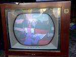
First thing I noticed is that no matter what I did to try and tune in the signal, it was always skewed off to one side and frequency response was terrible. I tried what the manual suggested and attempted to tweak the osc in the tuner and also tried the slug for the channel I was on (4), but no joy at all. This issue was still global in nature because it happened on any channel, so the problem was in the tuner or IF. It ended up being the core for the fine tuning coil had been tampered with; a few little turns put all my channels back where they should be, so I moved on to IF response. IF response actually wasn't too bad, but the tuner link was jacked. After sweep aligning those and making the peaks in the curve look right, I had a look at chroma response which only needed a slight tweak to the right side to get perfect. About 1.5 hours, and I was satisfied with the tuner/IF stuff. Chassis went back into the cabinet for a check. Another big disappointment: now I had nothing but a blank white screen...hmmm, had I completely gone wrong with the alignment? Nope, this problem ended up being the audio tube which was removed for alignment because it was causing strange interference with the signals. It was the buzz going through the speaker wires that radiated into the IF strip when the cover was off that was the problem, so I'd taken it out. Because it's part of the power supply circuit, I suspected putting it back in would have an effect. Boy, was I right! The bottom half of the audio output tube feeds the plate circuit of the 1st video amp (it's a sort of voltage divider I think), so no wonder it wasn't getting a picture. With the audio output back in and the IF shield installed, this is what I got!  Huge improvement now, it's starting to look like a real color TV. All the picture noise from before was now gone, and the fine tuning works like a champ. Colors lock solid right away, and sync is rock stable in vert and horizontal. Things that still need to be done to get the picture perfect: 1. CRT hasn't been degaussed at all, which is the reason for the random impurities with the color bars. 2. convergence is slightly off, but not enough to make me want to mess with it at this point. 3. The color bars on the left are not correct, which likely means the CW driver transformer needs a touch or two. I will probably perform a full chroma alignment on it, to make double sure things are in order. 4. I still only have about 18kv on the CRT anode, which causes the picture to bloom pretty bad at high brightness. Everything in the horizontal section looks good for right now, so I'm suspecting the HV regulator is not at the correct set point. Since this set has fixed HV regulation, I will have to mod the grid circuit of the 6BK4 to add a pot so I can adjust HV into range. It's pretty simple, just copy and paste the fixed 1.5m resistor and 500k pot in from the CTC-7 schematic. It goes from the grid to ground, shunting the B+ boost away and changing the bias of the tube. Hopefully I can get it to conduct less, and HV will come up a bit. I will monitor shunt reg cathode current before attempting this mod, to confirm my suspicions. 5. Probably need to go through the CRT drives, to make sure grey scale tracking is spot on. Hopefully after all that, I'll be able to post a proper set of Wingate color bars. 
__________________
Evolution...
|
|
#84
03-02-2012, 01:45 AM
|
||||
|
||||
|
Lookin' good Nick
 I'm glad it wasn't anything major. I'm glad it wasn't anything major. "go Cheech and Chong on me" - I gotta remember that 
|
|
#85
03-03-2012, 12:28 AM
|
||||
|
||||
|
Thanks Bob, so am I.
So I tried installing the HV pot, but it didn't make any difference. Even with the regulator not drawing any current at all with the set at minimum brightness, it still didn't go over 18kv. Also bumped up the horizontal drive by changing the value of a resistor on the horizontal board, but no dice- still only 18kv. I know the CTC-5 chassis is known to be a little on the weak side, but are they so weak they aren't able to put out the 20kv called for in the manual? Nothing I try seems to work, but at least horizontal output tube cathode current is staying under 200ma. If it turns out the HV really is weak and that's just the way it is, I guess I'll just have to live with it. But I'd prefer if I could get the full 20kv, I think it would bring a little more brightness to the table. I suppose I could try one of those more efficient stick HV rectifiers, but I doubt I'd get 20kv even with that. Need ideas.
__________________
Evolution...
|
| Audiokarma |
|
#86
03-03-2012, 05:33 PM
|
||||
|
||||
|
Quote:
Glad your fly didn't blow.
__________________
Tom C. Zenith: The quality stays in EVEN after the name falls off! What I want. --> http://www.videokarma.org/showpost.p...62&postcount=4
|
|
#87
03-03-2012, 05:54 PM
|
||||
|
||||
|
If anything, the screen voltages are a little high. With the brightness control at minimum, there's still a slight image on screen. The HV just needs to be stronger, there's no way it should be sagging like it is. I'm trying to get more info on the drive waveform, I think it might not have enough amplitude to drive the output tube hard enough. Right now I'm looking at about 150v p-p, and thinking there should be more. 200v p-p sounds more like it, but I know little about this chassis.
__________________
Evolution...
|
|
#88
03-04-2012, 05:38 PM
|
||||
|
||||
|
Today after I got the CT-100 cabinet settled in the living room, I worked installing horizontal drive and HV adjust pots. I put them on a piece of phenolic, mounted to the chassis with standoffs. I am now able to get a full 19.5kv, but am unsure what the horizontal cathode current is doing because I ran out of meters to attach to the chassis.
After I get back from church, I'll check cathode current to see what it's doing. Hopefully it's OK, and I can put this issue to rest.
__________________
Evolution...
|
|
#89
03-15-2012, 12:42 AM
|
||||
|
||||
|
Good news! The Wingate has been running pretty well for the past week or so, so I'm calling this one done. Between adjusting the horizontal drive and HV pots I installed, I was able to get a reliable 19.5kv anode under most viewing conditions. Sams shows a 110v p-p drive waveform as being correct, I ended up with 140v p-p because it made a greater amount of HV. The increased drive did not cause a drive line to appear. The horizontal cathode current settled right around 205ma, which is higher than I would like to see, but since the flyback is running pretty cool I'm just gonna leave it. The HV pot is almost at maximum (minimum current draw from the regulator), so 6BK4's should last forever in this set.
You could just about run without one and be fine, but I left it in for safety.I've come to the same conclusion as everyone else with this chassis: HV production is simply pathetic. At anything more than moderate brightness the picture blooms, HV sags, and the raster shrinks horizontally. It's impossible to get more than 20kv from the HV supply even with the 6BK4 removed, though HV does improve the longer the set operates. My suggestion to CTC-5 owners: it'll never make a bright picture, so thank your lucky stars RCA saw fit to put these chassis in the most aesthetically pleasing cabinets of all time. A fair trade, all things considered.
__________________
Evolution...
|
|
#90
03-15-2012, 09:04 PM
|
||||
|
||||
|
Sounds like a wrap to me Nick.
And I very much like your H drive and HV adjust mods. Next time you are over here you will have to draw the mods on my Sams for me.And also remember as the young wipper snapper that you are, you have been used to watching modern day tv sets that were more capable of producing a decent picture in a moderately lit room. Back in the day (yes I go that far back) us old farts were used to watching color tv in the evening, during prime time when colorcasts from the network were likely to be seen, and it was common to watch in a dimly lit (if not completely dark) room. So an expremely bright picture was not all that necessary. (IE: we didn't have to turn the brightness up so far that the picture was apt to bloom) In fact lots of people who had nearly dead picture tubes would postpone replacing the crt for years by letting the set warm up for a long period of time and then watching in a totally dark room so they could see the dim image on the weak crt. As a matter of fact, the picture actually looked better in a dimly lit room with the brightness at a low level. I made it a practice to keep the brightness down to a low level to help extend the life of the picture tube. (don't know if it made any difference on the extended life but it seemed to make sense to me as a young kid of 17 when we got our first color set)
__________________
Vacuum tubes are used in Wisconsin to help heat your house. New Web Site under developement ME http://AntiqueTvGuy.com Last edited by ohohyodafarted; 03-15-2012 at 09:11 PM.
|
| Audiokarma |
 |
|
|





 Linear Mode

