
|
|
|
#151
 01-24-2014, 08:01 AM
|
||||
|
||||
|
that convergence is as good as i ve ever seen.amazing its perfect!set looks great and i applaud your work.if i remember correctly,these sets had a different look as far as color fidelity.afterall,these were among the first color sets and there were many improvements to be made.overall,they had a nice look to them and i actually own one.mine is in climate controlled storage.restored by stan cash back in the 90s,the picture is beautiful.i got it due to the death of original owner.cabinet was restored and flawless.convergence is very good,but not quite as good as yours.that part of the job took stan many hours.he stated it was difficult to get it correct but its looks good.my crt is excellent.these are a wonderful piece of history and glad that another one is in operation.

|
|
#152
01-24-2014, 12:05 PM
|
|||
|
|||
|
Quote:
And BTW, the degree of convergence you've achieved on this set would pass muster on any roundie.
|
|
#153
01-24-2014, 01:07 PM
|
||||
|
||||
|
Quote:
An uncle of mine had one for a few weeks in 1954, this in Ft. Worth TX. This was a loaner while his mono giant console was being fixed. It looked just fine in color. In B&W the purity was less than perfect but watchable. Convergence I remember as no problem. He liked color so much that when the 21CT55 came out he bought one. In Ft. Worth we had the big advantage that all local programs were in color, right from day 1. And there were lots of studio productions. On the 21CT55 they looked fine too. I've told this story before. Oh but did I mention he was 1/2 mile from the transmitter? Doug McDonald
|
|
#154
01-24-2014, 02:03 PM
|
||||
|
||||
|
Quote:
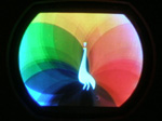
I bet your Uncle viewed this station break slide on his new 21CT55 back in late '54. -Steve D.
__________________
Please visit my CT-100, CTC-5, vintage color tv site: http://www.wtv-zone.com/Stevetek/ Last edited by Steve D.; 04-09-2016 at 03:19 PM.
|
|
#155
01-24-2014, 03:11 PM
|
||||
|
||||
|
Wow, what a nice set. the linearity of that test pattern is superb.. this set is older than my father!
I know the feeling of hearing, 'we're sitting down to dinner!' and all you want to do is just finish the damn thing already. BTW, I've seen CRT sets from the 1990s which had awfully misadjusted convergence. I have battled crt set-up on mostly rectangular sets and it really is a pain. From one Tom to another, excellent job 
|
| Audiokarma |
|
#156
01-24-2014, 04:44 PM
|
|||
|
|||
|
Wow what an accomplishment! Boy I'd love to come see your set in person someday. I believe I work in the same town as you. We might even be working for the same employer. I don't have the ability to collect and restore televisions since all of my time and space is taken up with 35mm movie and projector collecting. I "collect and restore" sets vicariously on this board through reading everyones posts and stories here. Congratulations on your remarkable achievement! -Sean
|
|
#157
01-24-2014, 04:45 PM
|
||||
|
||||
|
Quote:
Well, maybe on the loaner. It was months later that he got the 21 incher. Doug Mcdonald
|
|
#158
01-24-2014, 08:09 PM
|
||||
|
||||
|
Wow looks like you really got her humming!
__________________
Tom C. Zenith: The quality stays in EVEN after the name falls off! What I want. --> http://www.videokarma.org/showpost.p...62&postcount=4
|
|
#159
01-25-2014, 02:01 PM
|
||||
|
||||
|
I'd like to improve the color tracking a little more if I can. What I've noticed is that the color is quite good if the overall scene is dark, but on brighter scenes, the red becomes weak. What is peculiar to me is that the red becomes weaker in a bright scene than it is in a dark scene. For example, if there is some red lettering or a red object on the screen, and the rest of the scene shifts from darker to lighter, the red stuff actually gets dimmer. Likewise, a face that looks normal if the background is dark loses its red content if the background gets lighter, even though the brightness of the face is unchanged.
I'm wondering if there is a problem in my DC restoration circuitry (particularly for red), or if the DC restoration circuitry is having trouble dealing with the difference between the guns in my CRT? I've got the red screen at max, blue and green screens much lower, and both the blue and green drive below their original minimum settings (resistors modified). The red background with low brightness is too high, even though green and blue background are set at max. In general, the brightness control does not have the correct range -- it basically always needs to be fully clockwise, and still the image is a little dark, although not bad. Here is the data on the CRT (see pictures below: #1 red, #2 green, #3 blue). All three guns test with very high emission. Key difference is the cutoff bias: Red cutoff bias: -51.5 V Green cutoff bias: -66 V Blue cutoff bias: -67 V I also checked the screen voltage during the emission test on my CR-70: Red screen: 259 V Green screen: 188 V Blue screen: 225 V So although all three guns are capable of high emission, there are significant differences between them in terms of bias and screen current/voltage. Should the set be easily able to handle these differences within normal control ranges? Any indication of something not quite right in the video amplifiers or DC restoration circuits? If it's merely a matter of the set not being able to handle the gun differences within normal design range, I'd like to modify things to work better with the CRT in its current state, if I can figure out what would work. Since many of you have far more experience with color sets than I do, I thought one of you might have some ideas.
|
|
#161
01-25-2014, 10:21 PM
|
||||
|
||||
|
Quote:
Checked the screens of my 'benched' CTC2 and came up with: B8000194 G2 R 389 G 344 B 345 As you can see the levels are quite a bit higher. Although there are six feet of extra wire on the 15G, the 'bench' operation is normal and did not require a basic set up. Also, I dug up an unfinished CTC2 setup procedure from 2009 that never got put on my CT-100 site before it went down. Added some stuff and posted it here on AK: http://www.videokarma.org/showthread...98#post3093798 Pete
|
|
#162
01-25-2014, 10:31 PM
|
||||
|
||||
|
Also agree that the CRT is not the problem. I don't recall, have you replaced all the original white inductors in the chassis? Every single one of those was bad in mine, even one that tested good at the beginning of the resto went bad after the electrons started whizzing around. Don't trust them, they are always bad!
Have you tested the 6BC7 resto tube, or done any subbing yet? The schematic doesn't have 'drive' controls listed, so I assume you mean the video gain pots on the little phenolic boards. What are your actual G1 voltages doing with the chassis driving the CRT? If the voltages are wildly different, I'd expect to find trouble in the output circuits of the individual matrix channels. Not saying they are going to be exactly the same voltage, but the fact that you're having to mod things points to circuit troubles. Sams has the inductors on each matrix output at around 5 ohms (L54/55/56 respectively), but they are typically wound on high value resistors because they make a quick easy former. If a coil has opened up in the matrix output, there could still be some voltage getting through on just the resistor. Food for thought, ohm them out to check. This is very likely a DC voltage issue at the G1 terminals and not a video issue, the fact that the brightness isn't working correctly is a clue. All it does is set the DC offset on the G1's of the CRT, thereby varying their relative intensity. You could look at it as an adjustable cutoff control, if you like. Find your missing DC voltage, you'll likely find the problem.
__________________
Evolution... 
|
|
#163
01-26-2014, 02:22 AM
|
||||
|
||||
|
Thanks to both of you for the tips and measurements. I'm not sure why, but my CRT seems to need some extra help to produce a good picture. I wonder if it has just a touch of gas in it?
I was able to make quite a bit of progress after reading your posts above, and taking some time to understand the DC restoration and brightness circuitry in this set. Bottom line is that I had to make a modification to get the brightness into a usable range. I changed the value of R282 on the Sams schematic from 1.8 K to 900 ohms (put another 1.8 K in parallel) and this brought the brightness control into a normal range (or perhaps it even goes a little too bright at the top now). As you can see, the brightness control is at the bottom of a big voltage divider that starts with the screen controls connected to B+. The CRT cathodes are connected to the junction of the 1.8 K and 4K resistors, and were previously running about +135 volts. The brightness control couldn't bring the grids high enough. Changing the 1.8 K to 900 ohms brings the top of the brightness control closer to the cathode voltage (and lowers the cathodes to +124 V, more or less what the schematic says it should be). This allows me to run with normal brightness and not need excessive contrast just to make the picture bright. More on that in the next post on the function of the DC restorer. Other mods I previously made are shown here: To coax enough red out of this CRT and to tone down the green and blue, the blue and green gain control ranges have been modified (to allow further reduction) and the green background range has been modified. This provides good grayscale from black to white, as long as the contrast is not set too high. Not sure if the green background mod is really still needed at this point (I should try removing it).
|
|
#164
01-26-2014, 02:40 AM
|
||||
|
||||
|
The following scope pictures illustrate the behavior of the DC restorer in the CT-100, and also show why my picture turns green if the contrast is too high.
These are all shots of the red CRT grid signal. The brightness control and DC restorer (a separate diode for each CRT grid) set the level of the bottoms of the blanking pulses on the video. With the brightness all the way down, the bottoms of the blanking pulses are at zero (bottom of scope grid): The scope vertical scale is at 20 V / div. Increasing the brightness a little just moves the whole waveform up. In this case, so the bottoms are at 40 V: Now the brightness is set to a good point (bottoms of blanking pulses at 60 V), but the contrast is still fairly low. Note that the red cathode is at 124 V, near the top of the screen, so things are still pretty dark overall: Now I increase the contrast control, and you can see that the bottoms of the blanking pulses are still at 60 V (held there by the DC restorer) and the contrast grows the waveform upward for a brighter picture: Here is the point of maximum usable contrast, and the picture is quite good, with good greyscale color tracking. The tops of the waveform are now at or slightly above the cathode voltage, so this is the threshold for CRT grid current starting to flow: If I turn up the contrast more, grid current in the CRT pushes the whole waveform down. Since there is a 100 K ohm resistor going to the DC restorer cathode, the action of the DC restorer trying to maintain the bottoms of the blanking pulses at 60 V is now overcome by the lower impedance "grid leak" biasing of the waveform down by the CRT grid current: What this means is that a lot of the red content in the picture is now being pushed toward black, even though a few of the brightest red areas are at maximum brightness. The effect of this is to cause the whole picture to shift toward green and goof up the color balance. Since the green phosphor is capable of higher brightness at lower current, the green is no where near this kind of grid current situation, so the green keeps getting brighter while we start losing red. The contrast control can be advanced further still, driving the bottoms of the blanking pulses all the way down to zero on the red (and still topping out at around 130 -140 V), giving an extremely green picture. I suppose I really should have captured some screen shots along with the last two scope shots, but I trust you can imagine the problem. So with these modifications, I now get a well behaved picture if I turn up to the contrast just to the point that things start turning green, and back off a little. Good greyscale tracking, and colors stay pretty true from dark to bright. The picture is not all that bright, and is best viewed in a reasonably dark room. Not very viewable in a sun-lit room by any means. So I'm not sure why my CRT seems to need these circuit mods to work. There may yet be something wrong in the circuitry, but it looks from various voltage measurements and scope traces that the circuitry is doing what it should. By the way, the tip on the white coils was probably a good one. I do still have a few of those white coils in place, but I checked them again and they're still OK for the moment. In the video output stages, there are no white coils left. L51 and its brethren were bad when I got the set, so those have been replaced. L54 and its brethren are not white coils, but red ceramic coated ones that seem to be fine (maybe were previously replaced?). A few white coils still left in some other circuits. I also swapped the 6BC7 DC restoration tube for a brand new one, but that didn't have any positive effect. For completeness, here are some voltage measurements with the set running well at its optimal contrast point: Screen voltages: R: 448 V G: 275 V B: 306 V Cathodes: all at 124 V Grid voltages (varying with scene, of course, so don't pay too much attention other than the general range of these): R: 87 V G: 88 V B: 95 V Last edited by Tom Albrecht; 01-26-2014 at 03:29 AM.
|
|
#165
01-26-2014, 10:48 PM
|
||||
|
||||
|
One question that naturally arises when it seems that modifications are needed to generate what should have been possible with the original circuitry is "What's different now?"
One thing that has been apparent all through the restoration process is that the B+ voltage has been quite high on this set. The original selenium rectifiers had been replaced with silicon rectifiers at some point in the past, and that actually caused at least a 10% overshoot in the voltage. The RCA service manual shows the main B+ as 400 V, and Sams shows it as 380 V. I was getting 440 V. This played some role in why the brightness control range wasn't right, since it resulted in increased bias by virtue of having the CRT cathode about 10 volts higher than it should have been. This, combined with the fact that my red gun cuts off at about 50 volts instead of 68 volts like the other guns (and no doubt what the red gun did originally) was causing some problems. The previous power supply work had a pretty sloppy appearance, with the diodes and a bunch of power resistors added in the space where the seleniums had been. The original ballast is gone. I had left the previous work in place up until now since it was functional. But now that the high B+ is causing some problems, it's time to get the power supply producing the correct voltage. The main change, of course, was simply to add an appropriate power resistor in series with the AC feed to the silicon rectifier voltage doubler, as shown here: Using a value of 8 ohms brought the voltage down from 440 to 399 volts. I also put the fuse back into the circuit, since the previous modifications had removed it. If RCA felt there was a good reason to have a fuse in this circuit, I thought it would be best to put it back in there. The previously installed power resistors weren't quite the right values. In place of the 315 ohm ballast resistor, they had a 280 ohm resistor (two 560 ohm in parallel). In place of the 800 ohm ballast, they had 750 ohms (two 1500 ohm in parallel). These lower resistances further increased various power supply voltages. I put in the correct value resistors using combinations of power resistors to hit the values exactly. The 315 ohm needs to handle substantial dissipation. I have three 10 watters in series, and they get rather hot -- dissipating something like 25 watts total. The 8 ohm resistor also generates quite some heat. I have a 30 watt chassis-mount resistor in there, and the whole vertical sheet metal structure gets pretty hot. Those seleniums must have made pretty good spacer heaters as well as the big ballast tube used originally. "Before" and "after" shots of the power supply wiring are shown in the attached images. Lowering the B+ back to the correct target value should keep things running cooler in this set. With my solid state tripler, etc., the flyback was running pretty hot, so I'm glad to cool things down a bit. I was able to put the brightness modification back closer to the original, with the 900 ohm modified resistor I showed above now at 1100 ohms (originally 1800 ohms) and plenty of upside brightness range. An unfortunate side effect of lower the voltage this much, however, is that many adjustments were thrown out of whack. Convergence had to be redone among other things, but the second time around was certainly much easier than the first. I also had to lower my focus regulation zener string from 3000 V to 2800 V to get the focus range adjusted to the new reality. Picture quality is now very good, with good greyscale color tracking. The only real complaint one might have is that the picture is not very bright, but I understand that is par for the course with the CT-100. It serves best as a night-time TV. 
|
| Audiokarma |
 |
|
|








 Linear Mode

