
|
|
|
#46
 01-23-2014, 10:38 PM
|
||||
|
||||
|
Thanks! Finally time for the first power up.
 First a test with the fusistor pulled so no B+. After a little cable wiggling, they lit up.  Now with B+ and a raster appeared   Next with a signal applied. Horizontal sync is impossible to achieve.  Rotating the coarse hold control to one extreme, tweaking the hor. osc. and twiddling the hor. sync finally resulted in a somewhat stable image.  Swapping out a few IF tubes helped, but it still doesn't feel right. The sound is clean but not loud enough, the contrast is poor and the sync touchy. I suspect there's not enough gain somewhere. 

|
|
#47
01-25-2014, 07:17 PM
|
||||
|
||||
|
I switched to a different head unit with a good 21FDP4 in it and was surprised that it didn't look any better. The set takes about 5 minutes to fully warm up and stabilize and the picture isn't very sharp.
B+ is about 10% low which might account for these issues. First I think I'll try swapping out the ancient silicon rectifiers with some 1N4007s. 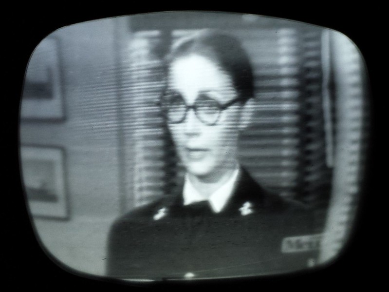
|
|
#48
01-25-2014, 08:35 PM
|
||||
|
||||
|
Just tested the original diodes and they're OK, but I'll try replacing them anyways. Something else odd. The total current draw is only 1.15A. It should be around 1.6A

|
|
#49
01-26-2014, 12:37 PM
|
|||
|
|||
|
Hi Bob and all,
I find these sets very appealing, mostly because of my engineering nature. But I wonder how these sets were used and how it was marketed. What would the consumer do other than just put the CRT on top of the cabinet? One could have kept the cabinet near a viewing chair and used the cabinet as a remote control - and not have to get up to change channels. One could have kept the cabinet inside the house and brought the CRT outside on the patio for watching TV outside. Is the speaker inside the cabinet of the CRT using? Any ideas why these sets were/are populate other than the novelty of it? -Steve
|
|
#50
01-26-2014, 03:07 PM
|
||||
|
||||
|
The speaker is inside the cabinet but there is an audio jack in the CRT base. I've never seen an actual external Philco speaker. They're much less common that than Holiday model that came out at the same time so I don't think they sold all that well.

Last edited by bandersen; 01-26-2014 at 07:03 PM.
|
| Audiokarma |
|
#51
01-26-2014, 07:02 PM
|
||||
|
||||
|
I believe this is what the speaker looks. I suppose that could just be any old generic speaker plugged into the base though.
|
|
#52
01-26-2014, 10:30 PM
|
||||
|
||||
|
I bit the bullet tonight and dissasembled the CRT housing so I can service the 2nd video amp. It's been partially recapped, but I can see an original electolytic in there.
 It actually was a lot easier because of a great tip posted recently (sorry can't remember the author). Instead of fighting to undo the stiff spring on the decorative gold band, leave it attached and slide the band over the plastic housing.  That needs a good cleaning   So does the inside of the rear cover.  There's an odd, faint "starburst" pattern on the CRT face  Finally, I can get at that little circuit.   Looks like the CRT was replaced in 1965 in LA. 
|
|
#53
01-27-2014, 09:04 AM
|
|||
|
|||
|
The small 'lytic, should have been changed, as well.
I like that shielded H.V. anode lead and the line interlock.
|
|
#54
01-27-2014, 02:46 PM
|
||||
|
||||
|
I tested that 4uF 'lytic and it's not leaky, but the power factor is around 20% so I'll replace it.
The plastic CRT cover is polishing up nicely with Novus #2. Here you can really see how dark the tint is.  001 by bandersen, on Flickr
|
|
#55
01-29-2014, 12:10 AM
|
||||
|
||||
|
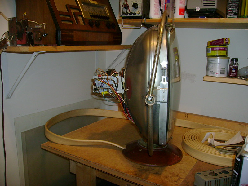
Here's a side view showing how short the CRT is.
|
| Audiokarma |
|
#56
01-31-2014, 12:28 PM
|
||||
|
||||
|
I noticed some corrosion on the plug and the cable is loose.
 So I opened it up and found it's much worse than I realized. The pins are corroded, screws are very rusty and it's been poorly rewired. Here's a nice, neat factory original for comparison. Now I can the see the rewired one is so loose because it should have a section of the vinyl outer jacket inside the plug.   After more examination, i decided to rewire it myself.  The point of no return   Here are the wires for AC line interlock, tube filament, audio, horizontal & vertical yoke, HV and video. 
Last edited by bandersen; 01-31-2014 at 12:36 PM.
|
|
#57
01-31-2014, 01:21 PM
|
||||
|
||||
|
That must have taken a few minutes to wire each one of those plugs at the factory.
|
|
#58
02-02-2014, 04:35 PM
|
||||
|
||||
|
Here it is cleaned up and ready for rewiring.
 Unfortunately, I discovered one of the pins had broken off and been replaced with a bit of bent wire. Not sure what to do about it.  Also spent some time troubleshooting the chassis. It takes several minutes for the horizontal to stabilize and even then it's very touchy. Also the 410 boost voltage is less than 300.  The horizontal is so touchy just bringing my hand near the tube has an effect.  That got me thinking one of the pins might be floating. Sure enough - pin 2 is open. There should be a 1Meg resistor between it and pin 7 of the AFC tube. It's buried inside one of the networks so I must have made a mistake somewhere  I tried tacking an external resistor between the tube sockets. It had a definite effect, but now I can't get hold lock at all. So much as I hate to do it, I'll have to pull the board again. Last edited by bandersen; 02-02-2014 at 10:51 PM.
|
|
#60
02-02-2014, 05:45 PM
|
|||
|
|||
|
Ditto here, it sure looks gold to me too.
|
| Audiokarma |
 |
|
|


 Linear Mode

