
|
|
|
#1
 11-11-2015, 02:02 PM
|
||||
|
||||
|
RCA 721TS Help
I started restoring my RCA 721TS and I'm not getting a raster on my screen. I've recapped the set, including all of the electrolytics. I have proper high voltage at the second anode (9000v) but my voltages at the crt socket aren't even close. Below is what I have:
Pin 1 -16.10 (should be 140V) Pin 2 -25.4 (should be 75V) Pin 10 377 (should be 290V) Pin 11 62.6V (should be 220V) Pin 12 -16.25V (should be 140V) What am I missing here? Any help would be appreciated as this set is in nice condition and I'd love to have it as my daily watcher as I begin other sets!! Thanks! 
|
|
#2
11-11-2015, 03:36 PM
|
||||
|
||||
|
Scott,
It looks like your 150V supply is messed up. Looking at page 19 of the Rider's information, check your connections associated with C116C (30uF) that is connected to the voltage divider network between R153A and R154A. Maybe you shuffled something around there during the recap. Here's the Rider's that I am referring to: http://www.earlytelevision.org/pdf/R...TV1.pdfhttp://
__________________
Sean - WØKPX
|
|
#3
11-11-2015, 03:54 PM
|
||||
|
||||
|
Sean,
Thanks for your help. I couldn't open up the link... Scott
|
|
#4
11-11-2015, 04:53 PM
|
||||
|
||||
|
There were some extra letters in there, try this one.
http://www.earlytelevision.org/pdf/R...-Rider-TV1.pdf
|
|
#5
11-11-2015, 05:44 PM
|
||||
|
||||
|
Thanks Eric! I double checked my work and don't see any errors. I will dig into this schematic and try to figure it out.
|
| Audiokarma |
|
#6
11-11-2015, 07:24 PM
|
||||
|
||||
|
Guess I should have tested that link before I posted. Did you test the resistors in the set? If R153A is open (1125 ohms) that would eliminate your 150V supply voltage and could drag it down negative which is what you are getting with the negative voltages on pins 1 (filament), 2 (grid), and 12 (filament). The voltage on pin 11 (cathode) will be dependent upon the setting of your brightness control.
__________________
Sean - WØKPX
|
|
#7
11-11-2015, 08:09 PM
|
||||
|
||||
|
Sean,
153A tests at 17.8k. Way off! Would being higher, not open cause these negative voltages?
|
|
#8
11-11-2015, 10:45 PM
|
||||
|
||||
|
Finally some life!
I found a 30 watt, 1200 ohm power resistor and put it in in place of 153A and got a raster. After some adjustments with the focus cool and ion trap, I got a picture. I do have multiple overlapping images, so should I suspect failure with the mica caps on the horizontal controls? Any adjustments with the horizontal frequency, range and drive makes no difference.
|
|
#9
11-11-2015, 11:52 PM
|
||||
|
||||
|
Quote:
If make sure resistors are good before trying the micas.
__________________
Tom C. Zenith: The quality stays in EVEN after the name falls off! What I want. --> http://www.videokarma.org/showpost.p...62&postcount=4
|
|
#10
11-12-2015, 12:30 AM
|
||||
|
||||
|
Yes, I would check resistors first. If no joy there, look at micas. There is a cluster of six micas near the horizontal adjusters.
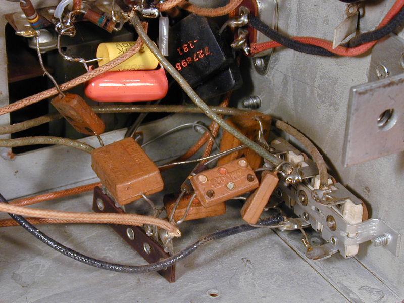 I ended up replacing all of them on my 721TCS. Phil Nelson Phil's Old Radios http://antiqueradio.org/index.html
|
| Audiokarma |
|
#12
11-12-2015, 01:02 AM
|
||||
|
||||
|
Are the images side by side or top and bottom?
In the picture you posted it looks more like the vertical is the problem (stacked top to bottom).
|
|
#13
11-12-2015, 10:24 AM
|
||||
|
||||
|
Eric,
The images are stacked vertically. I changed some out of tolerance resistors around the vertical hold control and vertical output tube, but no changes. I guess I will check resistors around the sync separator tube? Thanks, Scott
|
|
#14
11-12-2015, 10:39 AM
|
||||
|
||||
|
I would also check the capacitor values around the vert oscillator, an easy mistake is to use a cap of the wrong value, or a mislabled cap.
|
|
#15
11-12-2015, 01:37 PM
|
||||
|
||||
|
I changed a few caps in the vertical section and double checked my cap replacements. No changes, still double vertical images...
|
| Audiokarma |
 |
|
|


 Linear Mode

