
|
|
|
#31
 01-12-2016, 08:08 PM
|
||||
|
||||
|
Ok, after playing with the CRT socket, I've got the filament to light. The screen has not lit up yet. Now onto this problem...

|
|
#32
01-12-2016, 08:26 PM
|
||||
|
||||
|
Are you powering it up with the projection CRT? Be sure to keep it pointed away from you because of the X-Ray potential.
if it's in the barrel it should be pretty safe.
|
|
#33
01-12-2016, 09:09 PM
|
||||
|
||||
|
Yes, I'm testing it in the barrel, in the cabinet. Trying to figure out why my screen is dark. Undoubtedly a loss in high voltage, but what's causing it?
|
|
#34
01-12-2016, 09:36 PM
|
||||
|
||||
|
More often than not it's a lack of horizontal oscillator, I always start there.
Check for HV at the cap of the first HV rectifier (the one connected to the flyback) and see if you can draw an arc to an ungrounded screwdriver (a well insulated screwdriver). Just hold it near it and you should be able to draw a blue arc about a quarter inch long.
|
|
#35
01-13-2016, 09:34 AM
|
||||
|
||||
|
I havea s small blue arc off the 1b3 connected to the flyback. Fm audio comes in loud and clear, but no raster.
|
| Audiokarma |
|
#36
01-13-2016, 09:46 AM
|
||||
|
||||
|
Here is the section of the schematic either horizontal osc, output and afc....
|
|
#37
01-13-2016, 12:23 PM
|
||||
|
||||
|
If you have an arc at the cap of the 1B3 then you should have some HV, have you tested the 1B3's?
|
|
#38
01-13-2016, 04:50 PM
|
||||
|
||||
|
I can measure about 1000v off that particular grid cap. All three 1B3s test good.
|
|
#39
01-13-2016, 04:58 PM
|
||||
|
||||
|
Its probably not enough voltage to light the heaters in the HV rectifiers. You. Might still have a problem with the oscillator.
It could just be way off frequency. Or the B+ could be low. Last edited by Electronic M; 01-13-2016 at 06:16 PM. Reason: to merge duplicate posts
|
|
#40
01-14-2016, 02:05 PM
|
||||
|
||||
|
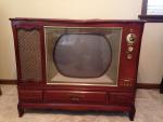
Here's an updated picture of the set back together and on. Fm radio comes in great, but still no picture. Still trying to trace down why...?
|
| Audiokarma |
|
#41
01-14-2016, 03:29 PM
|
||||
|
||||
|
Finally got a raster!! I found a 16.5 watt, 2450 ohm bleeder resistor on top of the horizontal output chassis. It was completely open and fed the oscillator circuit, along with the 1B3s. I had a ignite 50 watt adjustable power resistor that I was able to get pretty close. There's still a lot of adjustments to make and it's not as bright as it should be, but finally some encouraging progress!!
|
|
#42
01-14-2016, 07:04 PM
|
||||
|
||||
|
After playing with the horizontal frequency, I've got a picture. Getting the horizontal to hold for more than 3 seconds is what I'm battling right now.
|
|
#44
01-15-2016, 11:16 PM
|
||||
|
||||
|
Forgot I had this original ad. It will be nice displayed next to it and wow, $795!
|
|
#45
01-17-2016, 06:35 PM
|
||||
|
||||
|
I'm going to order mica caps for the horizontal hold circuit, should I order ones at 1,2 or 5% tolerance?
|
| Audiokarma |
 |
|
|




 Linear Mode

