Videokarma.org

Go Back   Videokarma.org TV - Video - Vintage Television & Radio Forums > Early B&W and Projection TV

Notices

We appreciate your help

in keeping this site going.
Reply
 
Thread Tools Display Modes
  #1  
Old 03-10-2017, 02:26 PM
old_tv_nut's Avatar
old_tv_nut old_tv_nut is offline
See yourself on Color TV!
 
Join Date: Jul 2004
Location: Rancho Sahuarita
Posts: 7,750
You are going into pin 4 (grid) of V4 (6AC7), right?

Did you disconnect the detector diode?

Also, .002 microfarad is too small to drive 5.6k. The low frequency cutoff will be about 14 kHz, causing vertical sync problems.

Since 5.6 k is close to your collector load, it will reduce the AC gain, so disconnect it and replace it with something like 56k. This will lower the cutoff to 1.4 kHz, still too high. Then, to get the low frequency response down to 30 Hz, the coupling cap has to be increased to 0.002x1400/30 = 0.09 (use 0.1 microfarad).
__________________
www.bretl.com
Old TV literature, New York World's Fair, and other miscellany

Last edited by old_tv_nut; 03-10-2017 at 02:39 PM.
Reply With Quote
  #2  
Old 03-10-2017, 05:06 PM
Phil Nelson's Avatar
Phil Nelson Phil Nelson is offline
VideoKarma Member
 
Join Date: Jan 2006
Posts: 4,030
Quote:
Originally Posted by old_tv_nut View Post
The 4.7 is 4.7 microfarads, right? The + side should be connected to the transistor base.
You are going into pin 4 (grid) of V4 (6AC7), right? Did you disconnect the detector diode?
Yes to all questions. 4.7 mfd electrolytic with + going to base.

Quote:
Originally Posted by old_tv_nut View Post
Since 5.6 k is close to your collector load, it will reduce the AC gain, so disconnect it and replace it with something like 56k.
There is no 5.6K resistor in the schematic supplied by vts1134. Do you mean R23 in the RA-102 schematic, the 5.6K connected to pin 4 of the 6AC7?

Thanks much for the various suggestions. I will tinker some more and report back (possibly tomorrow).

Phil Nelson

Last edited by Phil Nelson; 03-10-2017 at 05:19 PM.
Reply With Quote
  #3  
Old 03-11-2017, 09:51 AM
old_tv_nut's Avatar
old_tv_nut old_tv_nut is offline
See yourself on Color TV!
 
Join Date: Jul 2004
Location: Rancho Sahuarita
Posts: 7,750
Quote:
Originally Posted by Phil Nelson View Post

...

There is no 5.6K resistor in the schematic supplied by vts1134. Do you mean R23 in the RA-102 schematic, the 5.6K connected to pin 4 of the 6AC7?

...

Phil Nelson
Yes, exactly. For AC signals coupled through the amplifier output capacitor, the 5.6k appears to be in parallel with the collector resistor and lowers the gain. Also, the detector diode may present a non-linear load and distort the signal.
__________________
www.bretl.com
Old TV literature, New York World's Fair, and other miscellany
Reply With Quote
  #4  
Old 03-11-2017, 05:19 PM
Phil Nelson's Avatar
Phil Nelson Phil Nelson is offline
VideoKarma Member
 
Join Date: Jan 2006
Posts: 4,030
Progress! I replaced R23 with a 56K resistor and replaced the .002 coupling cap with an .01 cap. The picture was nice but the vertical was still somewhat unstable. I doubled the value of the coupling cap to .02 and now the vertical is very stable.

Here's the video signal direct from the generator:


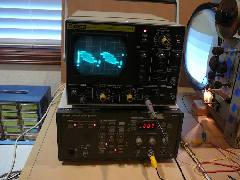
Here's the signal coming out of the preamp/inverter:


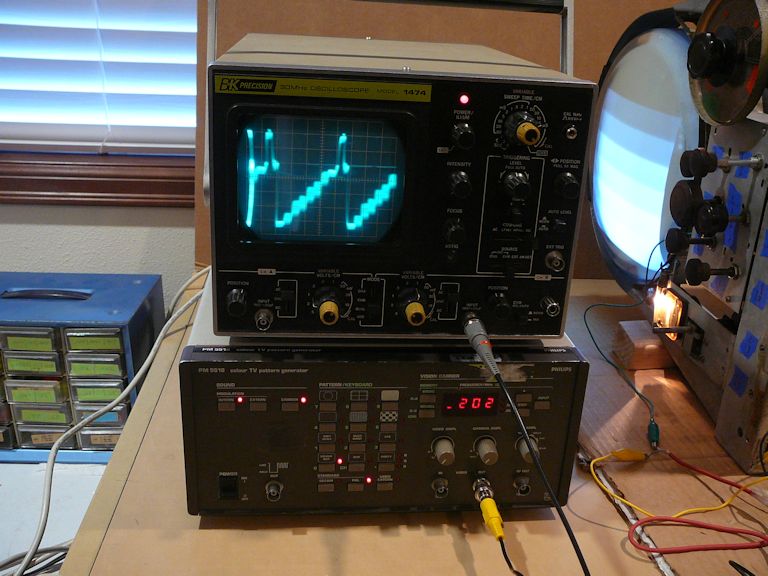
And here's a DVD using the preamp/inverter:


The screen image is so strong and bright that I had to turn it way down to avoid washing out in the photo.

I tried using a 9V battery in place of 12V, and it seems to work fine with 9V.

It would be nice to use this in a switchable A/V adapter like the one described in http://antiqueradio.org/A-V_AdapterForVintageTVs.htm . Then you can just flip a switch to change from A/V input to ordinary input from the antenna. Changing the value of R23 complicates that scheme, but I suppose there's a way.

If I installed this permanently in the chassis (with or without switching), it would be nice to find (or generate) a +9V source somewhere in the chassis rather than rely on a battery.

Phil Nelson
Reply With Quote
  #5  
Old 03-11-2017, 08:00 PM
old_coot88 old_coot88 is offline
VideoKarma Member
 
Join Date: Sep 2009
Posts: 2,645
Phil said:
Quote:
If I installed this permanently in the chassis (with or without switching), it would be nice to find (or generate) a +9V source somewhere in the chassis rather than rely on a battery.
You could rectify it right offa the 6.3V heater supply using a single diode and a filter cap. That's assuming one side of the supply is grounded. It would give you real close to 9V DC.
Reply With Quote
Audiokarma
Reply


Posting Rules
You may not post new threads
You may not post replies
You may not post attachments
You may not edit your posts

BB code is On
Smilies are On
[IMG] code is On
HTML code is Off

Forum Jump


All times are GMT -5. The time now is 04:31 AM.


Powered by vBulletin® Version 3.8.4
Copyright ©2000 - 2026, Jelsoft Enterprises Ltd.
©Copyright 2012 VideoKarma.org, All rights reserved.