
|
|
|
#1
 08-25-2006, 02:57 PM
|
|||
|
|||
|
Motorola Ballast tube
Does anybody have a source for a motorola ballast tube used in their 7" and 8" sets. It is of the 4 section type.
Thank you, Konrad Schiecke 
|
|
#2
08-25-2006, 09:21 PM
|
||||
|
||||
|
I bought one a few years ago from here:
http://www.oldradioparts.com/2a2fl.txt I don't know if they still have them. A much better option is to build a new ballast system with individual resistors, as detailed here... http://www.antiqueradio.org/motvt73.htm (thanks Phil!) Since even the NOS tubes can be bad from age. I have a bunch of info about the ballast tubes I posted here a while back, I'll try to find it if you're interested.
|
|
#3
08-26-2006, 08:52 AM
|
|||
|
|||
|
Thanks Max, Since i don't have a reference number the ballast site doesn't do me much good and I agree with your option to do it with individual resistors. Since i don't have a schematic yet for the motorola TS18a I just brought, I found reference to ballast tube resistances on another site to be, 100ohms between 6-7, 100ohms between 6-2, 38 ohms between 6-1 and 200 ohms between 4-3. Based on your knowledge is this correct? Thanks for you help.
Konrad Schiecke
|
|
#4
08-26-2006, 09:15 AM
|
||||
|
||||
|
Welcome Konrad. I believe the readings are near correct. The 100 ohms should be 105, and the 38 ohm should be 36 (?)
Frankly, the ballast tubes are not all that reliable. If you have a heater in any of the tubes fail, then change in current draw can destory the part of the ballast. All the tube consists of are some thin wires between mica plates. If you have the time and money, i would consider replacing it with some surface mount 25watt resistors. Phil Nelson ( a member here) has a great article on the restoration of a TS-18 channsis in a moto MV-73 here scroll down a bit to see how he replaced the ballast tube.
__________________
Jordan
|
|
#5
08-26-2006, 09:43 AM
|
||||
|
||||
|
Motorola TS18 Schematic
Quote:
I have the Sams Photofact for the TS18 chassis. If you want it, I will scan it and e-mail it to you free. Since Adam was kind enough to give me a knob for my Zenith color roundie, I want to return the favor by helping someone else.
__________________
Just look at those channels whiz on by. - Fred Sanford
|
| Audiokarma |
|
#6
08-26-2006, 10:43 AM
|
||||
|
||||
|
Ballast Tube Replacement
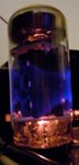
Amperite made a glass bulb replacement for the Motorola balast tubes, and gave them the same part number as Motorola:
17A485459 - For TS18 17A470303 - For VT71 The glass bulb was filled with an inert gas to aid in heat transfer, and should be more reliable than the open air balast tube. Check around with the variosu tube dealers out there... these show up from time to time.
__________________
John Folsom
|
|
#7
08-26-2006, 12:12 PM
|
|||
|
|||
|
Thanks Jordan,John and Compucat for your information. Compucat,I gladly accept your offer for a scan of the TS18A schematic. By e-mail is [email protected]
Konrad Schiecke
|
|
#8
08-26-2006, 12:31 PM
|
||||
|
||||
|
Welcome, Konrad to our Merrie Band of Iconoclasts...erm, old TV lovers... Are you in Germany ? We have a couple of TV guys from Germany here...One even went to the trouble & expense of bringing a CTC-5 to Germany, & got it going... Well, no matter where you are, welcome-again- & enjoy yr time here. I think you'll find this place is VERY habit-forming...<grin>
__________________
Benevolent Despot
|
|
#9
08-26-2006, 09:02 PM
|
||||
|
||||
|
Here is some detailed info about the ballast I posted a while back in this thread...
http://www.audiokarma.org/forums/showthread.php?t=50945 Here is some specific info on the resistors in the ballast in case anybody is interested. Somebody sent this to me a while back when I was working on this set, sorry but I don't remember who it was, or I would give them credit. "On the real Motorola VT71 schematic in Riders TV vol 2, they give a breakdown of the ballast, which they call R80. There are 5 sections to it. The AC input goes to pin 5, there are two 105 ohm sections from 5 to 2 and 5 to 7, there is a 37 ohm section from 5 to 1, a 200 ohm section between 3 and 4, and a 22 ohm section between 6 and 8. You will need to calculate the wattage and overrate by about 50% for a safety margin. The filament strings are each 300ma which gives you about 9 watts, so you need something in the 15 watt+ range for safety. I used two 50 ohm 10 watt resistors in series with a 10 ohm 5 watt resistor for each one of the 105 ohm sections. The 200 ohm section is the one that needs to be about 25 watts. For the 37 ohm section I used a 50 ohm 10 watt because I replaced the selenium rectifiers with silicon and needed the additional voltage drop there. The 22 ohm is a shunt across one of the tube filaments and you could get by there with a 20 ohm 5 watt. Because of the strange series/parallel filament strings in this set NEVER under any circumstances pull ANY of the tubes while the set is turned on. Many restorers choose to remove the CRT filament from the series string and add a small 6 volt filament transformer to power it, thus protecting the expensive CRT against accidental burnout due to failure in the series string."
|
|
#10
10-14-2010, 07:21 PM
|
||||
|
||||
|
Quote:
|
| Audiokarma |
|
#11
10-14-2010, 08:57 PM
|
||||
|
||||
|
I believe this is the video you are referring to. Jump ahead to about 3:30 for the ballast tube segment.
It's the 2nd part of a 3 part series I made while assembling a Motorola VT71.
|
|
#12
10-14-2010, 09:57 PM
|
||||
|
||||
|
While nitrogen is one of the gases used in lamps, Amperite ballasts typically use hydrogen or helium. Hydrogen isn't exactly inert, but it will prevent oxidation of tungsten and reduce any oxides. It also has a very high thermal conductivity. Amperite Ballasts
John Quote:
|
|
#13
10-16-2010, 10:58 AM
|
||||
|
||||
|
I'd like to hear if any of you that used wirewound resistors had trouble with the CRT filament getting light-bulb bright at power-up. About 25 years ago I used a mix of Clarostat vitreous enamel units plus a couple of ceramic ones pulled from a Heathkit AA-22. Seems the phrase "controlled heater warm-up time" was not applicable to the 7JP4, with the advent of specially-engineered series-string tubes years in the future...
I think the ballast was designed to absorb the current surge and protect the other heaters from doing the same. Great to hear about the Amperite relacement, I think that's a cheap price compared to replacing a 7JP4 with an open heater.
|
|
#14
10-17-2010, 02:10 PM
|
|||
|
|||
|
Hi everyone,
I just found this neat site. I bought a Motorola 9T1 on Friday with the TS-18A chassis and it too had a bad ballast tube. I think I will try to get a replacement and if unsuccessful give the power resistor solution a try. I need a copy of the schematic too and would appreciate receiving one. Anyone know what SAMs it is in? I couldn't find it in the SAMs index. Cheers, Joe
|
|
#15
10-17-2010, 03:16 PM
|
||||
|
||||
|
You can download the TS-18 schematic (Sams 83) here. http://www.earlytelevision.org/tv_sc..._diagrams.html
|
| Audiokarma |
 |
|
|






 Linear Mode

