Videokarma.org

Go Back   Videokarma.org TV - Video - Vintage Television & Radio Forums > Early B&W and Projection TV

Notices

We appreciate your help

in keeping this site going.
Reply
 
Thread Tools Display Modes
  #256  
Old 07-07-2011, 03:33 PM
vts1134's Avatar
vts1134 vts1134 is offline
Looking For Time
 
Join Date: Apr 2011
Location: Pittsburgh, PA
Posts: 1,534
Quote:
Originally Posted by jeyurkon View Post
There seems to be a design error here. The Sam's doesn't show what the HV is, but a 16GP4 typical operating voltage is 12KV. If they were actually operating it at 12KV, the Peak Inverse Voltage that the HV rectifier would see is slightly less than twice this. A little under 24KV.

The 1X2 is rated at 15KV PIV. So, it would break down. They're probably running the 16GP4 at 10KV or less, maybe 9.5KV. That would still cause the 1X2 to break down.

The 1X2-A, and 1X2-B are rated at 20KV PIV, the 1X2-C is rated at 22KV PIV.

If you can find a 1X2-A,B, or C then it would probably work without the modifications you made.

John
I have a 1X2B. According to my HV probe the 16GP4 is running at 14-15kv right now without the immediate sparking failure on the 1X2 which would be at 28-30kv PIV? It sounds like the 1X2 isn't going to last that long if I'm running it that far over spec. The CRT might not be happy running that far over spec either! One other thing that I have been pondering is what kind of X-ray emissions the 1X2 might be putting out with the voltage that high.
Reply With Quote
  #257  
Old 07-07-2011, 04:54 PM
old_coot88 old_coot88 is offline
VideoKarma Member
 
Join Date: Sep 2009
Posts: 2,646
Xray emission from the rectifier happens only during electron bombardment of the plate, which occurs only during the positive-going half cycle, and the max voltage is half the PIV value. The only real concern over Xrays was in color sets where 25KV on the pic tube anode was typical, and that hype was hugely overblown (IMHO). Heck, if Xrays were any danger i oughta have been thoroughly cooked many years ago.
Reply With Quote
  #258  
Old 07-07-2011, 04:57 PM
Electronic M's Avatar
Electronic M Electronic M is offline
M is for Memory
 
Join Date: Jan 2011
Location: Pewaukee/Delafield Wi
Posts: 15,445
I actually have a SS stick rectifier that I found in a box of tubes that I got for cheap in a swap meet donation auction. Not sure what to do with it, but will probably keep it as a diagnostic tool/spare for sets with open HV fill windings.

Tom C.
Reply With Quote
  #259  
Old 07-07-2011, 10:14 PM
jeyurkon's Avatar
jeyurkon jeyurkon is offline
VideoKarma Member
 
Join Date: Oct 2008
Location: Central Michigan
Posts: 1,699
Quote:
Originally Posted by vts1134 View Post
I have a 1X2B. According to my HV probe the 16GP4 is running at 14-15kv right now without the immediate sparking failure on the 1X2 which would be at 28-30kv PIV? It sounds like the 1X2 isn't going to last that long if I'm running it that far over spec. The CRT might not be happy running that far over spec either! One other thing that I have been pondering is what kind of X-ray emissions the 1X2 might be putting out with the voltage that high.
They list the maximum anode voltage for that CRT at 14KV. 15KV isn't going to kill it, but it doesn't help.

Does your probe have its own meter or does it plug in to your multi-meter?

old_coot88 is right about x-ray production only occurring during the positive going half cycle which causes electrons to bombard the plate. However, they don't even have half the PIV. The forward drop on these tubes is between 80-200 volts. The electrons only get accelerated to that energy. Those x-rays will never make it out of the 1X2.

If there was a failure of the 1X2 such that the forward drop was as high as half the PIV, then you'd have higher energy x-rays, but the cathode emission would be so low at this point that the x-ray dose rate would be very small because of the very low current.
Reply With Quote
  #260  
Old 07-08-2011, 06:02 AM
vts1134's Avatar
vts1134 vts1134 is offline
Looking For Time
 
Join Date: Apr 2011
Location: Pittsburgh, PA
Posts: 1,534
Quote:
Originally Posted by jeyurkon View Post
They list the maximum anode voltage for that CRT at 14KV. 15KV isn't going to kill it, but it doesn't help.

Does your probe have its own meter or does it plug in to your multi-meter?
I have to plug my probe into my meter. It may not be the worlds most reliable reading.

Thanks for the reassuring words on X-ray emissions. It kind of got me nervous when the last 1X2 I picked up had a warning painted right on the side of it about X-Rays.
Reply With Quote
Audiokarma
  #261  
Old 07-08-2011, 10:10 AM
old_coot88 old_coot88 is offline
VideoKarma Member
 
Join Date: Sep 2009
Posts: 2,646
Quote:
Originally Posted by vts1134 View Post
...I stopped at my local antique electronic shop (sorry just couldn't bring myself to go to Radio Shack) and get myself a handful of resistors.
While i share your disgustipation with RS on several levels, in many places they remain the only walk-in source of small parts like resistors, caps, fuses etc. ever since local parts houses went the way of the dodo bird. I grudgingly have to patronize RS pretty regularly. oc
Reply With Quote
  #262  
Old 07-08-2011, 11:07 AM
Phil Nelson's Avatar
Phil Nelson Phil Nelson is offline
VideoKarma Member
 
Join Date: Jan 2006
Posts: 4,030
Quote:
Originally Posted by roundscreen View Post
Check all the tubes in the if section and clean all the pins on the tubes in the if.
I'd extend that advice to all of the tubes. The first thing I do in every project (well, first after brushing away the dust) is to clean & test all tubes, as well as all controls & switches.

I remember the CTC-11's service switch well, and that's one reason why I've become eager to clean everything early. After recapping, the set worked very well except for one weird symptom. It was magically cured when Bill asked whether I had cleaned the service switch!

Phil Nelson
Reply With Quote
  #263  
Old 07-08-2011, 12:50 PM
vts1134's Avatar
vts1134 vts1134 is offline
Looking For Time
 
Join Date: Apr 2011
Location: Pittsburgh, PA
Posts: 1,534
Quote:
Originally Posted by Phil Nelson View Post
I'd extend that advice to all of the tubes. The first thing I do in every project (well, first after brushing away the dust) is to clean & test all tubes, as well as all controls & switches.
Phil Nelson
I'll get a brush and some contact cleaner going on all the tubes next time I have TV time. My rule is also test tubes first, it's just too bad it took me until post #115 to learn that this time around.
Reply With Quote
  #264  
Old 07-10-2011, 05:11 PM
vts1134's Avatar
vts1134 vts1134 is offline
Looking For Time
 
Join Date: Apr 2011
Location: Pittsburgh, PA
Posts: 1,534
Did a good cleaning of all of the tubes today. I also did a good scrubbing of the tuner. I tried moving the horizontal hold in both directions to the maximum. I also changed the channel on the tuner. All of which provided no video. The brightness control works and if I turn it up to maximum I have enough output to see through a phone book I think, the contrast has a very very minimum effect. I was wondering and wanted to ask all of you here is there some test I can run to verify the tuner itself is working versus the if stage not working? Another step I took while working on the underside of the set was to clean up some of my previous work. I decided that I would not accept the level of work I did on this set on future sets so why not start having that work ethic now.

Before:

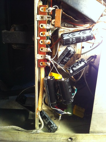
After:


One other note, I hooked up the speaker to the set and I am also not getting sound output. I do get a very low hum that increases with the set brightness. Can some one tell me what the term for this is called?
Reply With Quote
  #265  
Old 07-10-2011, 05:40 PM
old_coot88 old_coot88 is offline
VideoKarma Member
 
Join Date: Sep 2009
Posts: 2,646
Well first off, does your version of the set have the 'color' switch? If so, what happens when you click the switch back and forth? And does yours have the TV-phono switch? If so, what happens with the sound if you click this switch between TV/phono?

On the hum thingy with brightness, try turning the vert. hold from stop to stop. Does the hum change frequency ('pitch') or remain constant? If it remains constant, this tells you it's not vert. sweep bleed-through. oc
Reply With Quote
Audiokarma
  #266  
Old 07-10-2011, 06:03 PM
vts1134's Avatar
vts1134 vts1134 is offline
Looking For Time
 
Join Date: Apr 2011
Location: Pittsburgh, PA
Posts: 1,534
Quote:
Originally Posted by old_coot88 View Post
Well first off, does your version of the set have the 'color' switch? If so, what happens when you click the switch back and forth? And does yours have the TV-phono switch? If so, what happens with the sound if you click this switch between TV/phono?
Sorry should have mentioned that there is no color switch. I did clean the crap out of the TV/Phono switch. The is no difference in sound when I turn the TV/Phono switch back and forth, the raster just disappears.
Reply With Quote
  #267  
Old 07-10-2011, 06:30 PM
old_coot88 old_coot88 is offline
VideoKarma Member
 
Join Date: Sep 2009
Posts: 2,646
Hokay, how about checking the video detector diode (M4). While you got one end clipped loose, turn the set on and with a clip lead, intermittently short the grid of the 12AU7 1st video stage (V6) pin 2 to ground. Try this with the contrast control at both ends of its rotation. If the two video amp stages are working, there should be some very robust flashing of the raster.
Reply With Quote
  #268  
Old 07-10-2011, 08:14 PM
roundscreen roundscreen is offline
VideoKarma Member
 
Join Date: Oct 2003
Location: buffalo ny
Posts: 377
Do what OC suggested first... If a no go, Then you may not be getting b+ voltage to the tuner or the IF circuits. Check and see if the B+ is going into the tuner first and then check for correct voltage at the IF tubes. Look for open resistors in the power supply and the tuner / IF circuits... Be careful!!! The B+ power supply voltage is more dangerous than the high voltage due to the higher current in the B+ power supply.
Reply With Quote
  #269  
Old 07-10-2011, 10:44 PM
bandersen's Avatar
bandersen bandersen is offline
RCA 741PCS
 
Join Date: Mar 2009
Location: Chicago, IL
Posts: 8,813
That's what I've been thinking too - B+ isn't getting to part of the set. Less current draw would account for excessive voltage in the parts that are getting power.
__________________
Here are my Vintage Radio & TV YouTube Channel and Photo Gallery
Reply With Quote
  #270  
Old 07-11-2011, 07:04 AM
old_coot88 old_coot88 is offline
VideoKarma Member
 
Join Date: Sep 2009
Posts: 2,646
Y'know, the term "B plus" might be a little esoteric to a total Noob unless some background wuz provided on how the term came to be. Looks like he's hopelessly addicted to vintage TVs, and the term is gonna be ubiquitous to the addiction.
Anyhow, it harks back to the early days of radio, when radios ran on batteries. The tube filaments ran off a low voltage battery called the 'A' battery. The plates were supplied by a higher voltage source of 90V or more, called the 'B' battery. As radios evolved to run on house current, the plate source continued to be called the 'B' supply, and since it was of positive polarity, simply "B+". And the convention carried on into television practice.
Reply With Quote
Audiokarma
Reply


Posting Rules
You may not post new threads
You may not post replies
You may not post attachments
You may not edit your posts

BB code is On
Smilies are On
[IMG] code is On
HTML code is Off

Forum Jump


All times are GMT -5. The time now is 06:53 PM.


Powered by vBulletin® Version 3.8.4
Copyright ©2000 - 2026, Jelsoft Enterprises Ltd.
©Copyright 2012 VideoKarma.org, All rights reserved.