
|
|
|
#1
 06-06-2020, 12:13 AM
|
|||
|
|||
|
GE 14" Safety Question
So, I nabbed a pretty sweet little GE 14T007.
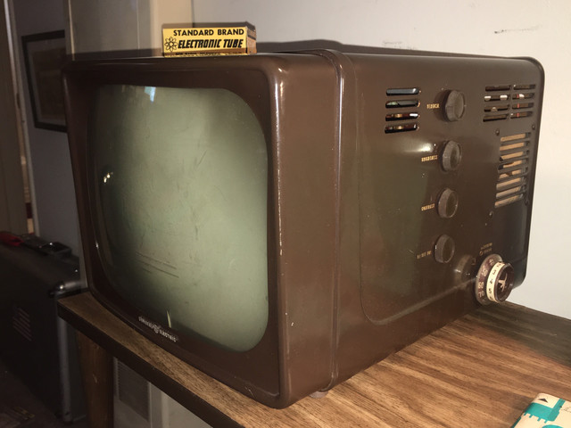 Although I currently am enjoying just admiring it on display, I do plan on embarking on a fair amount of testing. I'm fairly new to this hobby and haven't worked on anything like a GE, which has most of its components hidden on the other side of a chassis "firewall".  I want to put a CRT tester on it and then later test for at normal power for raster with test patterns and will want to discharge the CRT before removing the chassis. I don't see anyway to do that before doing so since I can't get to the anode from the back. Is there a safety concern in handling the chassis before the picture tube can be discharged? Last edited by Jon1967us; 06-06-2020 at 12:22 AM. 
|
|
#2
06-06-2020, 10:45 AM
|
||||
|
||||
|
Have you restored a vintage radio or two first? That is always a good start.
I wouldn't bother trying to power up the set before you at least replaced the electrolytic capacitors, you could damage expensive parts. Testing the CRT as well as the other tubes first is also a good idea. Clean up the interior is best done before you start the re-cap. When you pull the CRT socket off the tube be extra careful, if there is a bakelite tube base on the CRT it can come loose. It is a good idea to pry the base and the socket apart with a small screwdriver the first time at least, age can make the two stick together. Speaking of safety, be very careful with the neck of the CRT, the glass is the thinnest there, about as thick as a wine glass. The difference of air pressure due to the vacuum is almost 15 lbs per square inch. That means an area 8 inch square has a total pressure of about half a ton on it. This article by Phil Nelson (a member here) about a RCA set that has a similar cabinet and chassis construction. https://www.antiqueradio.org/RCA_14-...Television.htm
|
|
#3
06-06-2020, 11:28 AM
|
|||
|
|||
|
Yeah I’ve done some restoration and have some experience. Just haven’t worked on a set where the crt anode cap is inaccessible unless u remove the chassis. Just wondering if there’s a way to discharge everything before handling the chassis. Of course the chassis won’t be hot because of it not being plugged in but there may be a possiblilty of charge caps or crt.
|
|
#4
06-06-2020, 11:54 AM
|
||||
|
||||
|
Not familiar with this chassis, but it looks like the panel with the high voltage dischage label swings open to reveal the flyback and rectifier, so you can discharge at the rectifier output.
|
|
#5
06-06-2020, 05:52 PM
|
|||
|
|||
|
Quote:

|
| Audiokarma |
|
#6
06-06-2020, 08:19 PM
|
|||
|
|||
|
What makes this set even more rare is the UHF tuner. You rarely saw them until they were made mandatory in the 1960s (unless you had a dominant UHF station in your market). This set is definitely worth restoring if no major component is dead.
|
|
#7
06-06-2020, 09:04 PM
|
|||
|
|||
|
Quote:
|
|
#8
06-06-2020, 10:53 PM
|
||||
|
||||
|
I don't remember if you can remove the chassis from the back on this one, or if you have to remove the CRT and go out the front, either way you should be able to have enough slack to reach in and remove the anode connector from the tube, just slip a grounded screwdriver under the cap to discharge it.
You have to slide the yoke off the CRT as you go so loosen the clamp and remove it first,
|
|
#9
06-07-2020, 08:28 AM
|
||||
|
||||
|
Quote:
|
|
#10
06-07-2020, 10:43 AM
|
|||
|
|||
|
Quote:
The last one I took apart, I scrapped. The one shown is the real cheapie model, no handle! IDK if that's the early or late production? The early one uses a 5AN8 in the horiz AFC and audio IF, where the later one uses a 3AU6 and diodes for the AFC. I had a Motorola that was similar, but was a lot better.
|
| Audiokarma |
|
#11
06-07-2020, 08:34 PM
|
|||
|
|||
|
Thanks for the responses thus far!
I'm really in no hurry to jumpstart the TV, so I think I'm going to take my time and play it safe and at least test the filter and HV caps before proceeding. I do want to test the CRT, even though I've seen pics of it working from the previous owner. I have some problems with the CRT tester (B&K 465) and am prioritizing that a bit, replacing some aging components, such as totally open and dry Sprague Atoms, and treating oxidation. The meter is wacked out and quite inaccurate and so I probably need to replace diodes - but thats a topic for another time. BTW, I've taken a picture of the removal procedure from the Sams in case anyone's interested. Step 6 seems the most tricky! 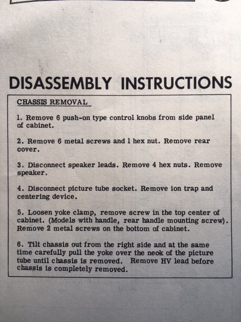 Someone mentioned the UHF tuner. Yes, it's pretty cool that it has that option, even though it seems like it's basically unusable these days (?) And, yes the UHF dial cord has broken off. Here's a pic of the dial cord diagram from the Sams... 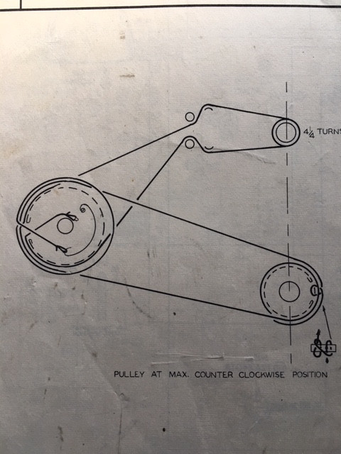 And here's the other side of the chassis, where the party's at. I'm pretty much all "Mousered Up" so I have what I need for a recap...Even a 1KV .015! 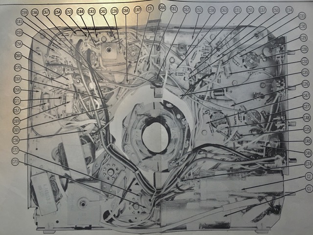
|
|
#12
06-07-2020, 08:41 PM
|
|||
|
|||
|
Quote:
No handle is right! More classy that way! Interesting info - Looks like late prod maybe - I'm seeing a 3AU6 for the audio IF.
|
|
#13
06-07-2020, 09:38 PM
|
||||
|
||||
|
Quote:
On my kcs96 (chassis wrapped around the picture tube neck) it didn't matter how many times I discharged the HV lead with the long screwdriver it still managed to zap me when I reached my arm in there to unhook it from the pic tube. On that set if I take the yoke off I can get my arm in there between the chassis and pic tube neck.
|
|
#14
06-07-2020, 10:28 PM
|
||||
|
||||
|
I have done 3 of these sets. You have the early version. Chassis removal is a pain....I think I got the chassis half way out such that I could reach the HV connector on the CRT and discharged it with a probe. I have the Beitmans service manual (a reprint of GE service manual) for the late set and it reccomends crushing defective original caps and resistors on the PCBs and twisting the old and new component leads together and soldering....I have to agree with that approach....the solder side of the PCB is blocked by the chassis and unscrewing the boards to get at the solder side usually destroys the factory board standoff grounds and involves unsoldering several wires...
Quote:
__________________
Tom C. Zenith: The quality stays in EVEN after the name falls off! What I want. --> http://www.videokarma.org/showpost.p...62&postcount=4
|
|
#15
06-07-2020, 10:37 PM
|
||||
|
||||
|
Quote:
you have not lived until POW-ZAP! your hair is standing on end!
__________________
=^-^= Yasashii yoru ni hitori utau uta. Asu wa kimi to utaou. Yume no tsubasa ni notte. いとおしい人のために
|
| Audiokarma |
 |
|
|








 Linear Mode

