
|
|
|
#16
 08-13-2026, 07:32 PM
|
||||
|
||||
|
Quote:
Take you multimeter and measure across the whole pot to see what the resistance is, and then measure between the wiper and either side. find a way to clip the meter leads onto the terminals of the pot and turn the pot from side to side while looking at the meter. You should see the resistance change smoothly from one end of the pot to the other. Based on what you have already said though, I would expect it to be completely shorted, or completely open if there's a problem with it at all. If you can confirm that's it's behaving like a normal pot, then you can pretty much assume it's not broken and move on. Looking at those other pictures, it seems like those old boards might need all the connectors cleaned really well, and the solder joints reflowed on anything that looks bad or is a physical connector. Solder joints tend to fail on parts that are either heavy or take abuse, like connectors that get done and undone, and big heavy parts like the flyback or transformer, or big power resistors. You also want to check things that get hot, especially if they have been darkened or burned. A lot of these kinds of issues will come down to basic stuff like that. Anything more advanced is probably going to require schematics. 
|
|
#17
08-15-2026, 09:00 AM
|
||||
|
||||
|
Quote:
__________________
Genesis does what Nintendon't Last edited by pac.attack76; 08-15-2026 at 09:05 AM.
|
|
#19
08-15-2026, 11:54 AM
|
||||
|
||||
|
It would probably take an afternoon to test every component on the board and reflow all of the solder.
Of course, the IC on the on board could also be at fault, which would be harder and possibly more expensive to replace, but it's worth spending a day and making one perfect board to test with first Without the schematics, I wouldn't know which pins on that IC to probe for a chroma waveform, but possibly one of the other guys here with more 70s TV experience remembers what IC it is and what it's doing But first things first; lots of these issues can be just bad solder joints and/or toasted passives
|
|
#20
08-15-2026, 09:59 PM
|
||||
|
||||
|
Ill try pulling that board and see what's on the other side. Doubt I'd ever find a replacement. Better if I can fix one of these since there's 2 of them.
__________________
Genesis does what Nintendon't
|
| Audiokarma |
|
#21
08-15-2026, 10:35 PM
|
||||
|
||||
|
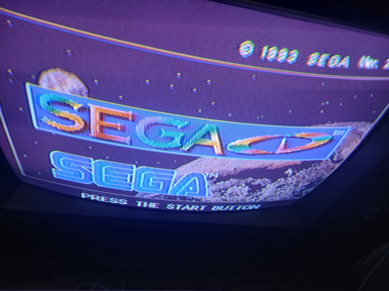
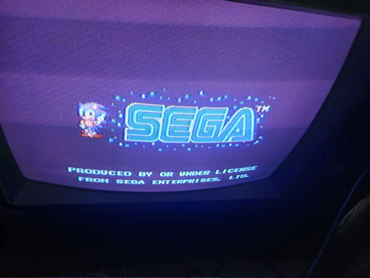
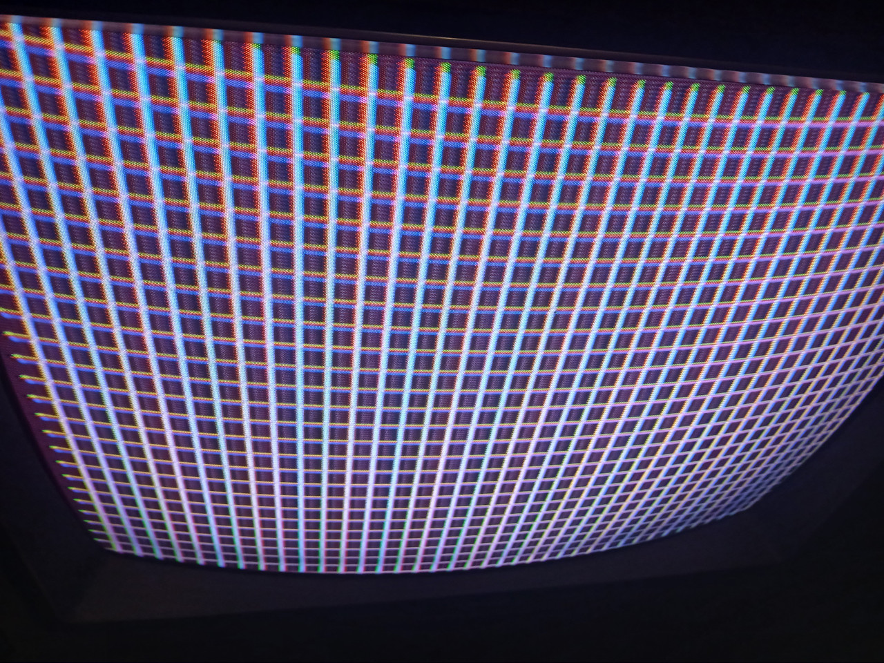
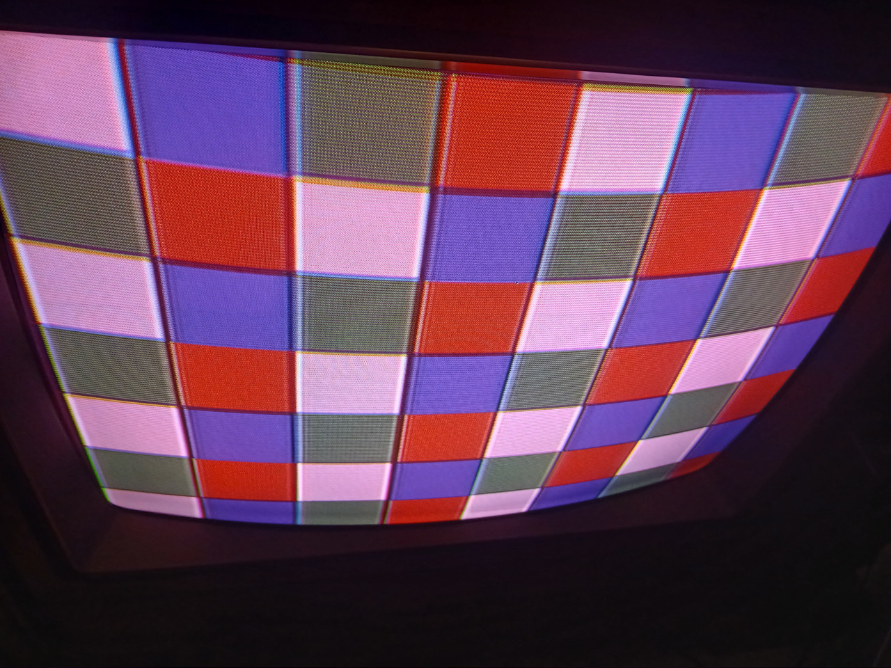
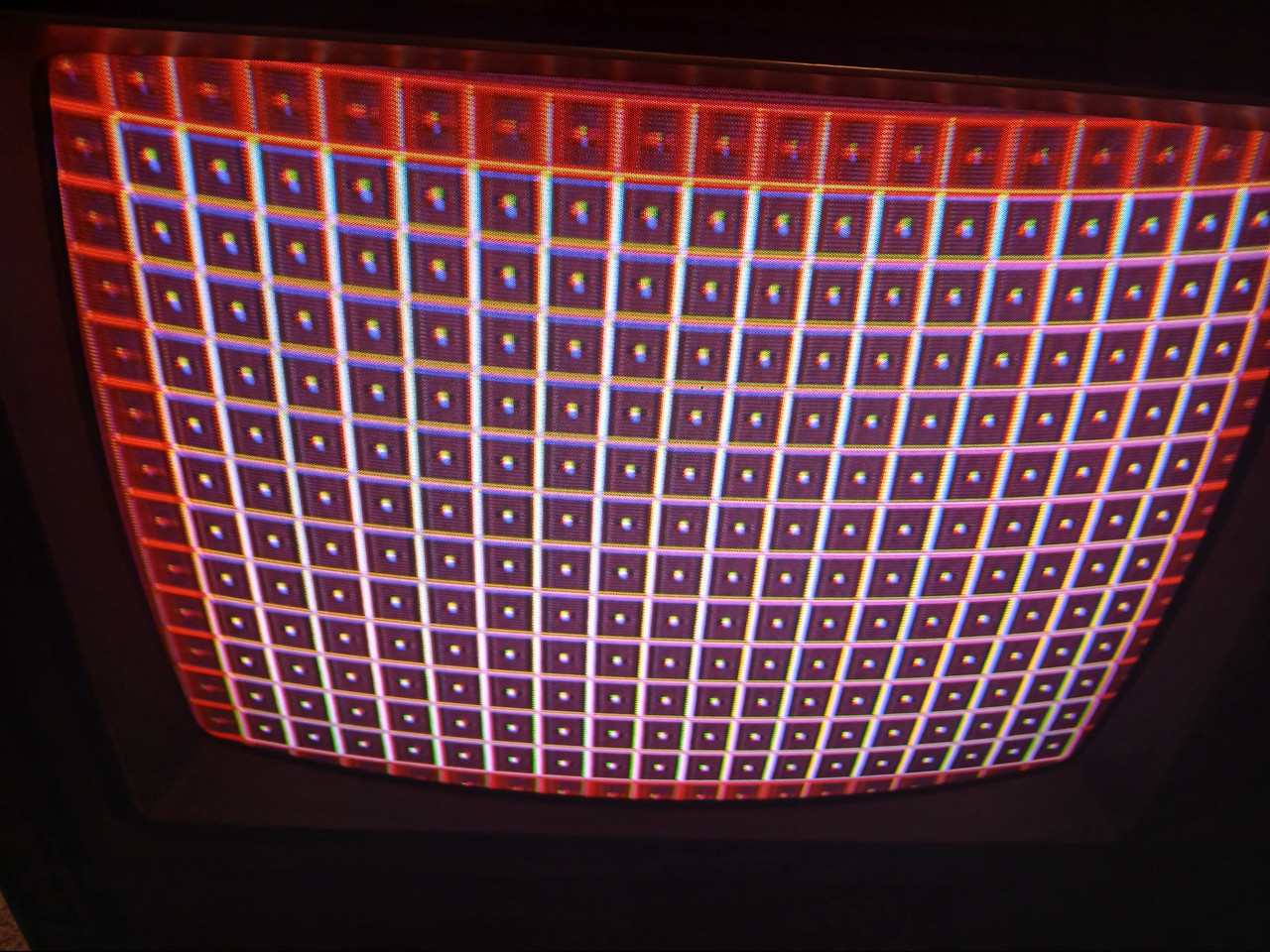
Ok, weird. Pulled board out and figured I'd put the old one in to see what happens. Had to set color and tint but here's what I got. Should I look at anything else before I close it up?
__________________
Genesis does what Nintendon't
|
|
#22
08-17-2026, 11:03 AM
|
||||
|
||||
|
Quote:
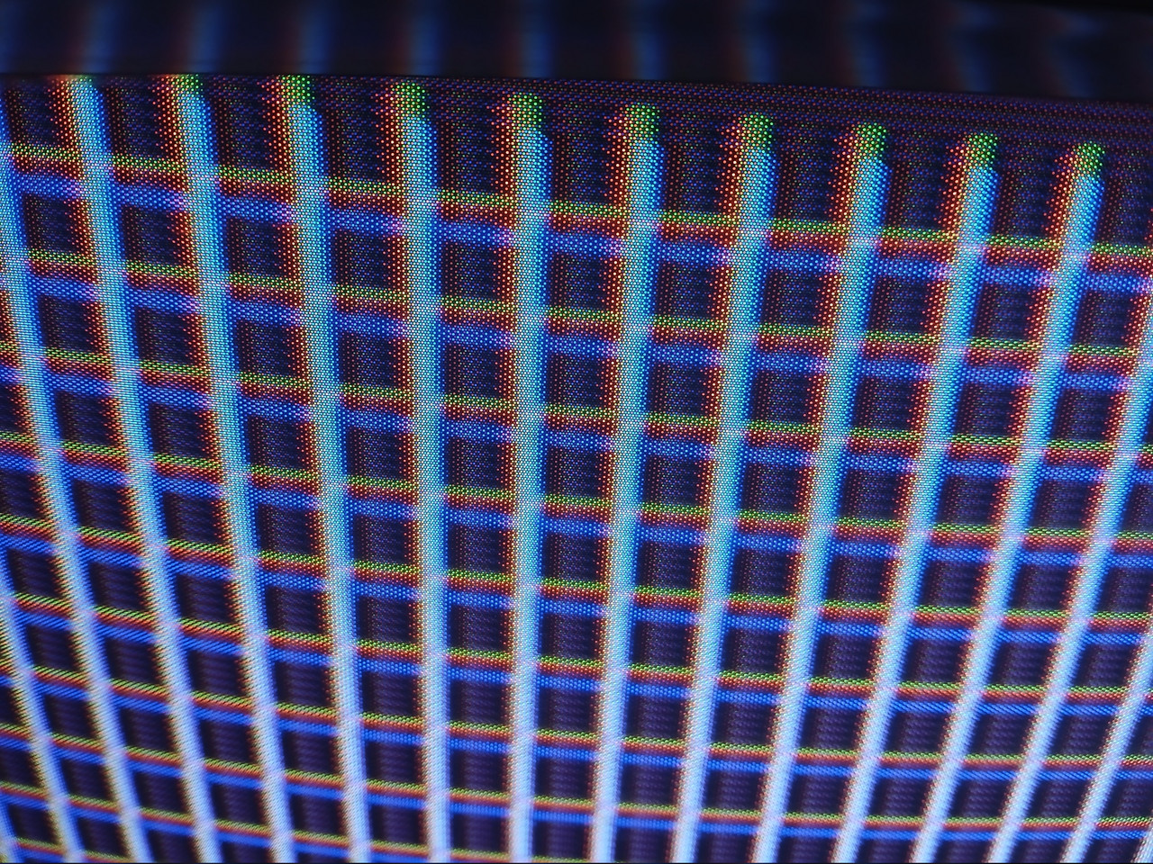
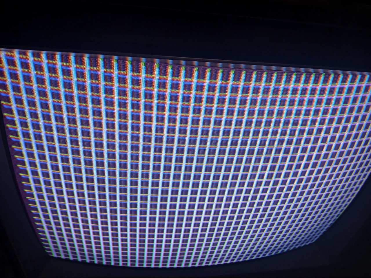
Also, your convergence is atrocious, so I would definitely dial that in with the yoke first. Caveat that yoke carries lethal voltages, so proceed at your own risk. Do whatever you have to do to learn how to handle it before you do anything.
|
|
#23
08-18-2026, 10:06 AM
|
||||
|
||||
|
Quote:
__________________
Genesis does what Nintendon't
|
|
#24
08-18-2026, 10:21 AM
|
||||
|
||||
|
Quote:
It can be very dangerous to move a yoke when the set is on. Make sure you know how to be safe. Consider just doing it in small steps while it's turned off and then checking it. It will take longer, but you also probably don't have the correct safety equipment to do this while it's on. The rings (maybe): I've never done an RCA before, but rings can be for both purity and convergence. Purity is the color uniformity across the entire screen that is effected by how far the yoke is pulled in or out from the base of the tube's neck. If you can imagine, when you pull the yoke in and out in line with the neck, the whole image will get bigger and smaller. However, the relationship between the position of the yoke and the tube will effect the spot that the beams land on the inside face of the tube because you are changing the geometry of the beam landing when you adjust the yoke. The purity rings basically allow you to dial in the beam landing by giving you some whole-screen adjustment for the purity. You generally adjust this by 1. setting the purity rings to dead center, 2. putting up the three color (R, G, B) stripe pattern on the screen, and then pulling the yoke in and out until the stripes are dead even, 3. putting up an all white image and adjusting the purity rings until the image is totally white on the sides. The convergence can be set by rings, but it can also be set by a potentiometer. This is almost always found on a box attached to the flyback or tripler, or it's found on the neck board. I've personally never seen one anywhere else. When it's a potentiometer, it's just the horizontal convergence, and the remaining rings set the vertical. So what I think your rings probably are is two for the purity and two for the vertical convergence, and there's probably a dial inside somewhere that does horizontal. But that's just a guess based on other sets I've done from the same time period. I've never worked on an RCA before, and sets in the 70s tended to be less similar in design than they became later on. Again, I've never worked on an RCA before, but I would guess that the rear two of the four rings would be the vertical convergence, just from experience. The rings closest to the base of the neck are typically the purity rings, assuming it has them. If you do end up messing with it, I would recommend picking up some thick electricians rubber gloves to move the rings. They are not foolproof, but they will at least keep you aware of your hands and what you are touching. I personally still use them. I also use an isolation transformer so that the TV is not directly connected to the power grid. Last edited by vol.2; 08-18-2026 at 10:33 AM.
|
|
#25
08-18-2026, 07:04 PM
|
||||
|
||||
|
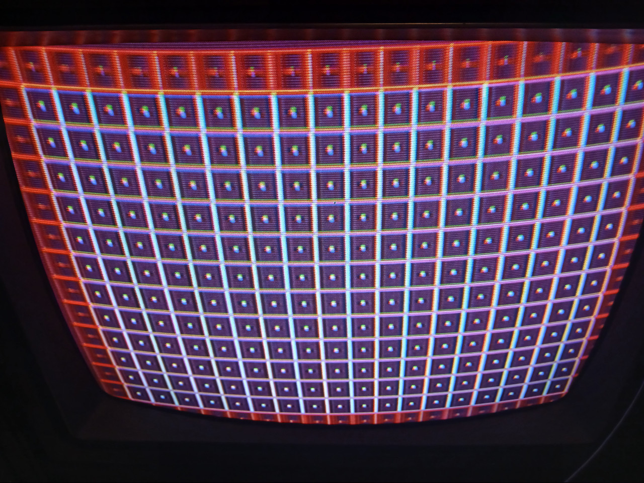
Now its tilting down like it was when I got it. I dont see any change really but maybe you can.
__________________
Genesis does what Nintendon't
|
| Audiokarma |
|
#26
08-19-2026, 09:35 AM
|
||||
|
||||
|
Quote:
|
|
#27
08-19-2026, 05:45 PM
|
||||
|
||||
|
Quote:
__________________
Genesis does what Nintendon't
|
|
#28
08-19-2026, 06:45 PM
|
||||
|
||||
|
Quote:
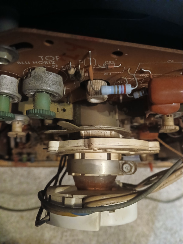
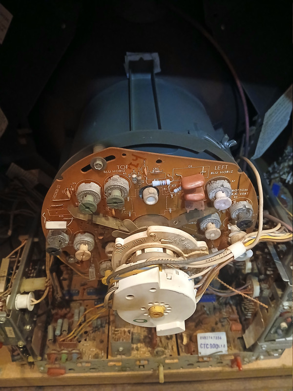
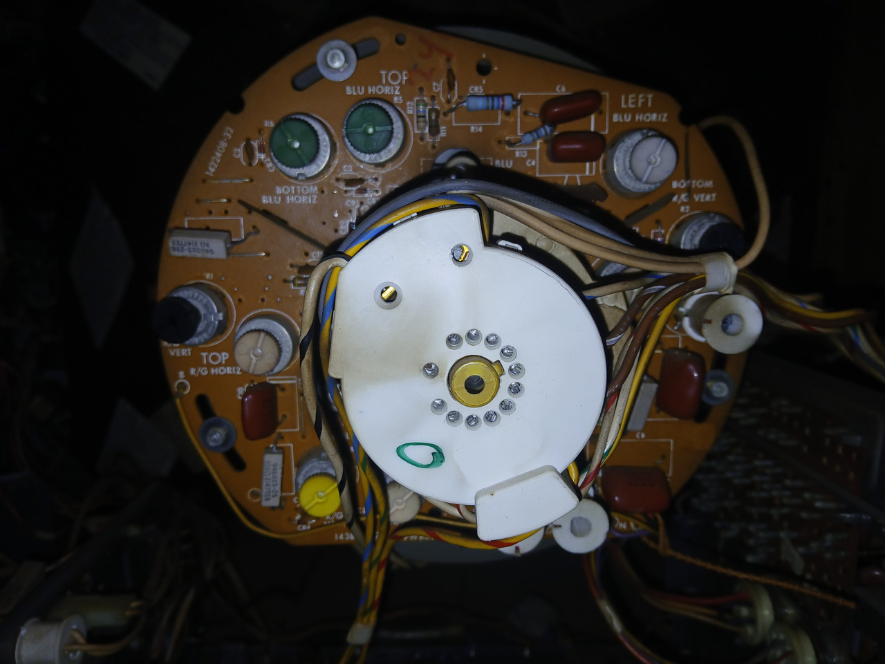
I would assume that your set is not supposed to adjust with yoke movement if you're not getting any change. I know there are such designs, but I've not worked on one before. Sorry, I'm not there in person, so I made an assumption that I shouldn't have. Looking at the pictures of your neck board, there appears to be knobs that relate to the convergence. I think that is where your solution lies. Do your best to document the effect of each knob before you go messing around with them. A good approach is to make a mark on the knob and the PCB so that you can return each one to it's starting position if necessary. Sometimes I will do that with tape so I can remove it when I'm satisfied.
|
|
#29
08-19-2026, 07:07 PM
|
||||
|
||||
|
Ok ill check these one at a time after I mark them.
__________________
Genesis does what Nintendon't
|
 |
|
|


 Linear Mode

